
MC68VZ328 Integrated Processor User's Manual


8-16 MC68VZ328 User’s Manual
Programming Model
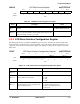
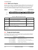
8.3.10 LCD Polarity Configuration Register
The LCD polarity configuration (LPOLCF) register controls the polarity of the interface signal that goes to
the LCD panel. The bit assignments for the register are shown in the following register display. The
settings for the bits in the register are listed in Table 8-11.
LPOLCF LCD Polarity Configuration Register 0x(FF)FFFA21
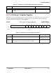
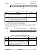
8.3.11 LACD Rate Control Register
The LCD alternate crystal direction rate control (LACDRC) register is used to control the alternate rates of
the liquid crystal direction. The bit assignments for the register are shown in the following register display.
The settings for the bits in the register are listed in Table 8-12 on page 8-17.
BIT 7654321BIT 0
LCKPOL FLMPOL LPPOL PIXPOL
TYPE
rw rw rw rw
RESET
00000000
0x00
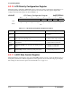
Table 8-11. LCD Polarity Configuration Register Description
Name Description Setting
Reserved
Bits 7–4
Reserved These bits are reserved and should
be set to 0.
LCKPOL
Bit 3
LCD Shift Clock Polarity—This bit controls the polarity of the
active edge of the LCD shift clock.
0 = Active negative edge of LCLK.
1 = Active positive edge of LCLK.
FLMPOL
Bit 2
Frame Marker Polarity—This bit controls the polarity of the
frame marker.
0 = Frame marker is active high.
1 = Frame marker is active low.
LPPOL
Bit 1
Line Pulse Polarity—This bit controls the polarity of the line
pulse.
0 = Line pulse is active high.
1 = Line pulse is active low.
PIXPOL
Bit 0 Pixel Polarity—This bit controls the polarity of the pixels.
0 = Pixel polarity is active high.
1 = Pixel polarity is active low.