
MC68VZ328 Integrated Processor User's Manual

8-10 MC68VZ328 User’s Manual
Programming Model
8.3 Programming Model
The remaining sections of this chapter provide detailed descriptions of the registers, their settings, and
sample programming examples.
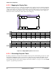
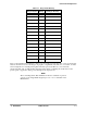
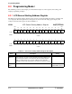
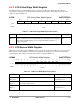
8.3.1 LCD Screen Starting Address Register
The LCD screen starting address (LSSA) register is used to inform the LCD panel where to fetch the data
to be displayed. The bit assignments for the register are shown in the following register display. The
settings for the bits in the register are listed in Table 8-2.
LSSA LCD Screen Starting Address Register 0x(FF)FFFA00
BIT
31
30 29 28 27 26 25 24 23 22 21 20 19 18 17
BIT
16
SSA
31
SS
A30
SS
A29
SS
A28
SS
A27
SS
A26
SS
A25
SS
A24
SS
A23
SS
A22
SS
A21
SS
A20
SS
A19
SS
A18
SS
A17
SSA
16
TYPE rw rw rw rw rw rw rw rw rw rw rw rw rw rw rw rw
RESET
0 00000000000000 0
0x0000
15 14 13 12 11 10 9 8 7 6 5 4 3 2 1 0
SSA
15
SS
A14
SS
A13
SS
A12
SS
A11
SS
A10
SS
A9
SS
A8
SS
A7
SS
A6
SS
A5
SS
A4
SS
A3
SS
A2
SS
A1
TYPE rw rw rw rw rw rw rw rw rw rw rw rw rw rw rw
RESET
0 00000000000000 0
0x0000
Table 8-2. LCD Screen Starting Address Register Description
Name Description Setting
SSAx
Bits 31
–1
Screen Starting Address 31
–1—This field is the screen starting address
of the LCD panel. The LCD controller will start fetching pixel data from sys-
tem memory at this address. This field must start at a location that will
enable a complete picture to be stored in 1 Mbyte memory boundary
(A[19:00]). In other words, A[31:20] has a fixed value for a picture’s image.
See description.
Reserved
Bit 0
Reserved This bit is reserved
and should be set to 0.