
Specifications


2
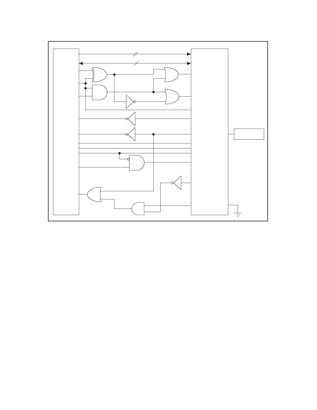
Figure 1. MC68340 and TNT4882 Interface Hardware Diagram
Synchronous Bus Operation
TNT4882 Address Lines
Address lines A6-A2 of MC68340 connect directly to the address lines of TNT4882. Although TNT4882 only requires
32 bytes of address space a total of 256 bytes are assigned. To take advantage of the longword instructions in
MC68340, TNT4882 FIFOs must be aligned on a word boundary. For this reason the A6-A2 lines of MC68340 are
connected to A4-A0 lines of the TNT4882 chip. Thus every TNT4882 register is assigned to four consecutive address
location for a total of 256 bytes.
TNT4882 Data Lines
Since the TNT4882 has built-in transceivers, the data lines connect directly to the CPU without requiring any external
pull-up resistors. All TNT4882 registers require 8-bit transfers except FIFO B that allows both 8-bit and 16 bit data
transfers. 8-bit I/O accesses can use either data bus. The selection of the data bus is controlled by the ABUSN and
BBUSN signals. The only allowed 16-bit accesses are reads and writes to FIFO B. ABUSN and BBUSN must both be
asserted during 16-bit I/O accesses.
MC68340 TNT4882AQ
5
16
RESETN
CSN
ABSUN
RESETN
CSN2
A0
SIZ0
DSACKN1
BBUSN
RDY1
CPUACC
PAGED
XTAL1
40 MHz CMOS
OSCILLATOR
INTR
DRQ
DAKN
WRN
RDN
DATA15-0
ADDR4-0
IRQN3
DREQN1
DSN
DACKN1
R/W
D15-0
A6-2