
Personal Computer - Word Processor User Manual

Software Design
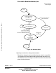
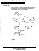
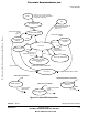
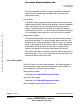
State Diagram
DRM028 — Rev 0 Designer Reference Manual
MOTOROLA Software Design 91
5.5.1 Initialize MCU
This state is entered after the MCU is reset, and performs the following
actions:
• MCU ports are configured for the application
• Some application (system) variables are initialized
• MCU clock PLL is locked
• Hardware boards used are identified, and parameters initialized
• PC master communication software is initialized with SCI port
• ADC is initialized
and the state is exited.
5.5.2 Initialize Application
This state is used as an application reset, called following a return from
fault or stop states.
In this state the following actions are done:
• Current measurement path calibrated and checked for error
• Some application (system) variables initialized
• Some MCU peripherals are configured (timer, OC function, PWM)
• PWM outputs for motor control are turned OFF
• Timer 1 (Tim A Ch1) is synchronized with the PWM cycle
• Speed input, dc-bus voltage and temperature measurement is
initialized
• Ready LED is turned ON
and the state is exited.
5.5.3 Stand-By
State diagram for this software is shown in Figure 5-8.
Frees
cale Semiconductor,
I
Freescale Semiconductor, Inc.
For More Information On This Product,
Go to: www.freescale.com
nc...