
Personal Computer - Word Processor User Manual

Software Design
State Diagram
DRM028 — Rev 0 Designer Reference Manual
MOTOROLA Software Design 89
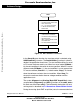
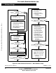
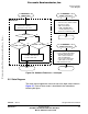
Figure 5-6. Software Flowchart — Interrupts
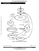
5.5 State Diagram
The motor control application can be in one of the eight states shown in
Figure 5-7. Each of these states is described in the subsections
following the figure.
INTERRUPT
PWM RELOAD
BEMF ZERO CROSSING
RTI
INTERRUPT
TIMER 1 (TIM A CH1)
CURRENT MEASUREMENT ISR:
RTI
SENSE ZERO CROSSING INPUT:
– TAKE 3 ZC INPUT SAMPLES
– BEMF STATE = S1&S2 | S2&S3
BEMF state
0
1
V_TASC = ris. edge
YES
NO
V_TASC = fal. edge
YES
NO
SET ZERO CROSSING GET:
– SET ICR_F - ZERO CROS. GET
– T_ZCROS = TIMER2 TIME
– START ADC DC-BUS CURRENT CHANNEL
– SERVE VIRTUAL TIMER3
– CURR = VALUE FROM ADC
–IF CURR > CURR_MAX_FAULT:
SET OVC_F (OVERCUR.) FLAG
– SET NEXT ADC CHANNEL NXT_CHNL
INTERRUPT
TIMER 2 (TIM A CH3)
COMMUTATION ISR:
RTI
– IF CMTE_F (COMMUTATION ENABLED):
DO MOTOR COMMUTATION STEP
TIMER 1 CURRENT SENSING TO
PWM SYNCHRONIZATION
SET PC_F (PHASE COMMUTATED)
T_CMT = TIMER 2 ACTUAL TIME
– ZERO CROSSING SELECTION
SENSING ISR:
Frees
cale Semiconductor,
I
Freescale Semiconductor, Inc.
For More Information On This Product,
Go to: www.freescale.com
nc...