
Personal Computer - Word Processor User Manual

Software Design
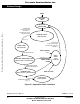
Data Flow
DRM028 — Rev 0 Designer Reference Manual
MOTOROLA Software Design 81
5.3.6 Process Commutation Time Calculation, Corrective Calculation 1, Corrective
Calculation 2
These processes provide calculations of commutation time intervals
(periods) (Per_ZCros, Per_ZCrosFlt), from captured time (T_Cmt,
T_ZCros, T_ZCros0), and sets Timer 2 with variable T2. These
calculations are described in 3.3.1.5 Starting — Commutation Time
Calculation and 3.3.1.3 Running — Commutation Time Calculation.
5.3.7 Process Desired Speed Setting
The desired speed, held in register Speed_Desired, is calculated from
the following formula:
Speed_Desired = Sp_Input*Coef_Speed_Inp/255 +
Speed_Min_U8
5.3.8 Processs Speed Control
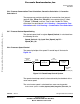
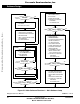
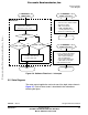
The general principle of the speed PI control loop is illustrated in
Figure 5-3.
Figure 5-3. Closed Loop Control System
The speed closed loop control is characterized by the feedback of the
actual motor speed.
The actual motor speed is calculated from zero crossing period:
Actual motor speed = 256*Per_Speed_MAX_Range/Per_ZCrosFlt_T2
(OutReg_U8)
(256*Per_Speed_MAX_Range/Per_ZCrosFlt_T2)
-
REFERENCE
SPEED
(Speed_Desired)
SPEED
ERROR
PI
CONTROLLER
PWM
DUTY CYCLE
CONTROLLED
SYSTEM
ACTUAL MOTOR
SPEED
Frees
cale Semiconductor,
I
Freescale Semiconductor, Inc.
For More Information On This Product,
Go to: www.freescale.com
nc...