
Personal Computer - Word Processor User Manual

DRM028 — Rev 0 Designer Reference Manual
MOTOROLA Software Design 75
Designer Reference Manual — Sensorless BLDC Motor Control
Section 5. Software Design
5.1 Contents
5.2 Introduction. . . . . . . . . . . . . . . . . . . . . . . . . . . . . . . . . . . . . . . .75
5.3 Data Flow . . . . . . . . . . . . . . . . . . . . . . . . . . . . . . . . . . . . . . . . .75
5.4 Main Software Flowchart . . . . . . . . . . . . . . . . . . . . . . . . . . . . .83
5.5 State Diagram. . . . . . . . . . . . . . . . . . . . . . . . . . . . . . . . . . . . . .89
5.6 Implementation Notes. . . . . . . . . . . . . . . . . . . . . . . . . . . . . . .103
5.2 Introduction
This section describes the design of the software blocks of the drive. The
software will be described in terms of:
• Data Flow
• Main Software Flowchart
• State Diagram
For more information on the control technique used see 3.3 Used
Control Technique.
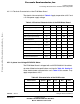
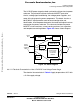
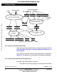
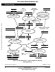
5.3 Data Flow
The control algorithm obtains values from the user interface and
sensors, processes them and generates 3-phase PWM signals for motor
control, as can be seen on the data flow analysis shown in Figure 5-1
and Figure 5-2.
Frees
cale Semiconductor,
I
Freescale Semiconductor, Inc.
For More Information On This Product,
Go to: www.freescale.com
nc...