
Personal Computer - Word Processor User Manual

Hardware Design
Designer Reference Manual DRM028 — Rev 0
74 Hardware Design MOTOROLA
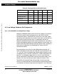
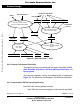
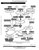
4.6.2 3-phase BLDC Low Voltage Motor with Motor Brake
The Low Voltage BLDC motor-brake set incorporates a 3-phase Low
Voltage BLDC motor EM Brno SM40N and attached BLDC motor brake
SG40N. The BLDCmotor has six poles. The incremental position
encoder is coupled to the motor shaft, and position Hall sensors are
mounted between motor and brake. They allow sensing of the position if
required by the control algorithm, which is not required in this sensorless
application. Detailed motor-brake specifications are listed in Table 2-4,
Section 2.
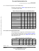
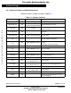
Table 4-6. Electrical Chatacteristics of the 3-Ph BLDC
Low Voltage Power Stage
Characteristic Symbol Min Typ Max Units
Motor Supply Voltage Vac 10 12 16 V
Quiescent current
I
CC
—175 — mA
Min logic 1 input voltage
V
IH
2.0 — — V
Max logic 0 input voltage
V
IL
——0.8 V
Analog output range
V
Out
0—3.3V
Bus current sense voltage
I
Sense
—33 —mV/A
Bus voltage sense voltage
V
Bus
—60 —mV/V
Peak output current
(300 ms)
I
PK
——46 A
Continuous output current
I
RMS
——30 A
Brake resistor dissipation
(continuous)
P
BK
——50 W
Brake resistor dissipation
(15 sec pk)
P
BK(Pk)
——100W
Total power dissipation
P
diss
——85 W
Frees
cale Semiconductor,
I
Freescale Semiconductor, Inc.
For More Information On This Product,
Go to: www.freescale.com
nc...