
Personal Computer - Word Processor User Manual

BLDC Motor Control
Designer Reference Manual DRM028 — Rev 0
52 BLDC Motor Control MOTOROLA
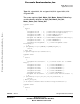
3.4.1.3 PC Master Software, BLDC Control MCU Software API, Communication Variables
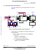
The application interface, data variables used for the exchange between
the BLDC control MCU software and PC master software, are shown in
Table 3-2. These variables are used for status sensing and control. PC
master software accesses these bytes directly from their physical
memory addresses.
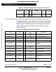
Set manual
mode
02 None
Setting of manual
mode
00
55
OK
Failed
Table 3-1. PC Master Software Communication Commands
Command
Comman
d
Code
Data
Byte
s
Demo
Suitcase Action
Respon
s
Byte
Response
Descriptio
n
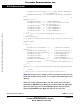
Table 3-2. PC Master Software API Variables
Name Type
I/
O
Representing
Range
Description
Sys3 Sys3_Def
I/
O
8flags System variable #3
Motor_Ctrl Motor_Ctrl_Def I 8flags Motor control variable
Motor_Status
Motor_Status_D
ef
O 8flags Motor status variable
Failure Failure_Def O 8flags Failure variable
Sp_Input U8 I < 0; 255>
Speed input variable used for
required
speed calculation
Speed_Range_Max_RP
M
U16 O
< 0; 65535>
[rpm]
Speed range maximum
Speed_Max_RPM U16 O
< 0; 65535>
[rpm]
Maximal speed limit
Speed_Min_RPM U16 O
< 0; 65535>
[rpm]
Minimal speed limit
Commut_Rev U8 O < 0; 255> Commutations per motor revolution
Curr S8 O
<-Curr_Range_Max_c
A;
Curr_Range_Max_cA)
dc-bus current
Curr_Range_Max_cA S16 O
<-32768;32767>
[A*10^-2]
Current range maximum
[A*10^-2]
Frees
cale Semiconductor,
I
Freescale Semiconductor, Inc.
For More Information On This Product,
Go to: www.freescale.com
nc...