
Personal Computer - Word Processor User Manual


BLDC Motor Control
Designer Reference Manual DRM028 — Rev 0
48 BLDC Motor Control MOTOROLA
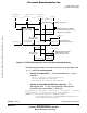
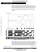
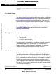
Figure 3-19 demonstrates the back-EMF during the start up. The
amplitude of the back-EMF varies according to the rotor speed. During
the starting (back-EMF acquisition) state the commutation is done in
advance. In the running state the commutation is done at the right
moments.
Figure 3-19. Back-EMF at Start Up
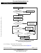
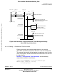
Figure 3-20 illustrates the sequence of the commutations during the
starting (back-EMF acquisition) state. The commutation times T2[1] and
T2[2] are calculated without any influence of back-EMF feedback. The
commutation time calculations are explained in the following section.
RUNNINGALIGN
BACK-EMF ZERO CROSSINGS
IDEAL COMMUTATION PATTERN WHEN POSITION IS KNOWN
REAL COMMUTATION PATTERN WHEN POSITION IS ESTIMATED
PHASE BACK-EMFS
PHASE A
PHASE C
PHASE B
.................
C
TOP
C
BOT
A
TOP
B
TOP
C
TOP
B
TOP
A
BOT
B
BOT
C
BOT
A
BOT
C
TOP
C
BOT
A
TOP
B
TOP
B
TOP
A
BOT
B
BOT
C
BOT
A
BOT
C
TOP
STARTING (BACK-EMF ACQUISITION)
FIRST SECOND THIRD FOURTH
Frees
cale Semiconductor,
I
Freescale Semiconductor, Inc.
For More Information On This Product,
Go to: www.freescale.com
nc...