
Personal Computer - Word Processor User Manual


BLDC Motor Control
Used Control Technique
DRM028 — Rev 0 Designer Reference Manual
MOTOROLA BLDC Motor Control 41
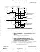
• BLDC motor commutation service
• Back-EMF zero crossing moment capture service
• Calculation of commutation time
• Interactions between these commutation processes
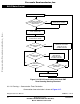
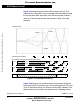
From diagrams an overview of how the commutation works can be
understood. After commuting the motor phases, there is a time interval
(Per_Toff[n]) when the shape of back-EMF must stabilized (after the
commutation the fly-back diodes are conducting the decaying phase
current; therefore, sensing of the back-EMF is not possible). Then the
new commutation time (T2[n]) is preset. The new commutation will be
performed at this time if the back-EMF zero crossing is not captured. If
the back-EMF zero crossing is captured before the preset commutation
time expires, then the exact calculation of the commutation time (T2*[n])
is made, based on the captured zero crossing time (T_ZCros[n]). The
new commutation is performed at this new time.
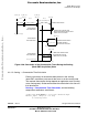
If for any reason the back-EMF feedback is lost within one commutation
period, corrective actions are taken in order to return to the regular
states.
The flowchart explaining the principle of BLDC commutation control with
back-EMF zero crossing sensing is shown in Figure 3-16.
Frees
cale Semiconductor,
I
Freescale Semiconductor, Inc.
For More Information On This Product,
Go to: www.freescale.com
nc...