
Personal Computer - Word Processor User Manual

BLDC Motor Control
Designer Reference Manual DRM028 — Rev 0
38 BLDC Motor Control MOTOROLA
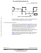
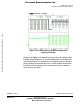
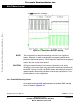
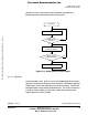
Figure 3-13. The Zero Crossing Detection
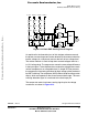
3.3 Used Control Technique
3.3.1 Sensorless Commutation Control
This section concentrates on sensorless BLDC motor commutation with
back-EMF zero crossing technique.
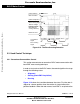
In order to start and run the BLDC motor, the control algorithm has to go
through the following states:
• Alignment
• Starting (Back-EMF Acquisition)
• Running
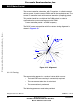
Figure 3-14 shows the transitions between the states. First the rotor is
aligned to a known position; then the rotation is started without the
position feedback. When the rotor moves, back-EMF is acquired so the
Phase Selection
MUX Command
Phase Comparator
Output
(Zero crossing edge)
Reference Level
"Branch" Voltage
(Interval of phase
Back-EMF zero
crossing detection)
Commutation
Signal
Zero Crossing
Signal
90°
Frees
cale Semiconductor,
I
Freescale Semiconductor, Inc.
For More Information On This Product,
Go to: www.freescale.com
nc...