
Personal Computer - Word Processor User Manual

BLDC Motor Control
Designer Reference Manual DRM028 — Rev 0
34 BLDC Motor Control MOTOROLA
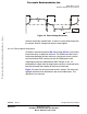
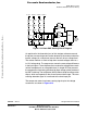
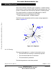
Figure 3-9. Mutual Capacitance Model
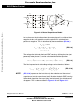
Let us focus on the situation when the motor phase A is switched from
negative dc-bus rail to positive, and the phase B is switched from
positive to negative. This is described by these conditions (EQ 3-8.):
(EQ 3-8.)
The voltage that disturbs the back-EMF sensing, utilizing the free (not
powered) motor phase C, can be calculated based the equation:
(EQ 3-9.)
The final expression for disturbing voltage can be found as follows:
(EQ 3-10.)
NOTE: (EQ 3-10.) expresses the fact that only the unbalance of the mutual
capacitance (not the capacitance itself) disturbs the back-EMF sensing.
When both capacities are equal (they are balanced), the disturbances
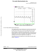
disappear. This is demonstrated in Figure 3-10 and Figure 3-11.
u
Ccb
B
C
A
R
C
C
C
C
R
C
R
C
u
/2
d
=
+
-
u
/2
d
=
+
-
u
Cba
I
d0
S
At
S
Bt
S
Ab
S
Bb
I
Sb
i
C
i
Cab
i
C
u
Cac
u
VC Cap
u
VB
u
VA
S
Ab
S
Bt
, PWM←
u
VA
1
2
---u
d
–
1
2
---u
d
→=u
VB
1
2
---u
d
1
2
---u
d
–→=,
i
Cac
i
Ccb
i
C
==
u
VC Cap
1
2
---u
Ccb
u
Cac
2R
C
++()u
Ccb
R
C
+()–
1
2
---u
Cac
u
Ccb
–()==
u
VC Cap
1
2
---
1
C
ac
--------
1
C
cb
--------–
i
C
td
∫
1
2
---
C
cb
C
ac
–
C
cb
C
ac
⋅
----------------------
i
C
td
∫
==
Frees
cale Semiconductor,
I
Freescale Semiconductor, Inc.
For More Information On This Product,
Go to: www.freescale.com
nc...