
Personal Computer - Word Processor User Manual

BLDC Motor Control
Designer Reference Manual DRM028 — Rev 0
30 BLDC Motor Control MOTOROLA
After evaluation the expression of the branch voltage u
Vc
is as follows:
(EQ 3-4.)
The same expressions can also be found for phase A and B:
(EQ 3-5.)
(EQ 3-6.)
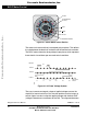
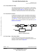
The first member in the equation (EQ 3-6.) demonstrates the possibility
to indirectly sense the back-EMF between the free (not powered) phase
terminal and the zero point, defined at half of the dc-bus voltage (see
Figure 3-5.). Simple comparison of these two levels can provide the
required zero crossing detection.
As shown in Figure 3-5, the branch voltage of phase B can be sensed
between the power stage output B and the zero voltage level. Thus,
back-EMF voltage is obtained and the zero crossing can be recognized.
When L
cb
= L
ab
, this general expressions can also be found:
(EQ 3-7.)
There are two necessary conditions which must be met:
• Top and bottom switches (in diagonal) have to be driven with the
same PWM signal
• No current goes through the non-fed phase that is used to sense
the back-EMF
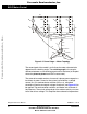
Figure 3-6 shows branch and motor phase winding voltages during a
0–360° electrical interval. Shaded rectangles designate the validity of
the equation (EQ 3-7.). In other words, the back-EMF voltage can be
sensed during designated intervals.
u
VC
3
2
---u
backEMF c
1
2
---L
ac
L
bc
–()
id
td
----–=
u
VA
3
2
---u
backEMF a
1
2
---L
ba
L
ca
–()
id
td
----–=
u
VB
3
2
---u
backEMF b
1
2
---L
cb
L
ab
–()
id
td
----–=
u
Vx
3
2
---u
backEMFx
where x A B C,,==
Frees
cale Semiconductor,
I
Freescale Semiconductor, Inc.
For More Information On This Product,
Go to: www.freescale.com
nc...