
Personal Computer - Word Processor User Manual

BLDC Motor Control
Brushless DC Motor Control Theory
DRM028 — Rev 0 Designer Reference Manual
MOTOROLA BLDC Motor Control 29
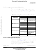
3.2.4.1 Stator Winding Equations
The BLDC motor is usually very symmetrical. All phase resistances,
phase and mutual inductances, flux-linkages can be thought of as equal
to, or as a function of the position θ with a 120° displacement.
The electrical BLDC motor model then consists of a set of the following
stator voltage equations (EQ 3-1.).
(EQ 3-1.)
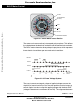
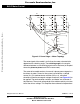
The task of this section is to explain the background of the back-EMF
sensing and to demonstrate how the zero crossing events can be
detected. Parasitic effects that negatively influence the back-EMF
detection are discussed and their nature analyzed.
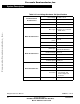
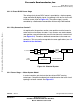
3.2.4.2 Indirect Back EMF Sensing
Let us assume a usual situation, where the BLDC motor is driven in
six-step commutation mode using PWM technique, where both top and
bottom switches in the diagonal are controlled using the same signal (so
called “hard switching PWM” technique). The motor phases A and B are
powered, and phase C is free, having no current. So the phase C can be
used to sense the back-EMF voltage. This is described by the following
conditions:
(EQ 3-2.)
The branch voltage u
Vc
can be calculated using the above conditions,
(EQ 3-3.)
u
Sa
u
Sb
u
Sc
R
S
i
Sa
i
Sb
i
Sc
td
d
Ψ
Sa
Ψ
Sb
Ψ
Sc
+=
S
Ab
S
Bt
, PWM←
u
VA
1
2
---u
d
+
−
=u
VB
1
2
---± u
d
=,
i
Sa
i
Sb
–i==i
Sa
di
Sb
d–id==,
i
Sc
0=i
Sc
d0=,
u
backEMF a
u
backEMF b
u
backEMF c
++ 0=
u
VC
u
Sc
1
3
---u
backEMF x
xa=
c
∑
L
ac
L
bc
–()
id
td
---- u
VC
–+–=
Frees
cale Semiconductor,
I
Freescale Semiconductor, Inc.
For More Information On This Product,
Go to: www.freescale.com
nc...