
Personal Computer - Word Processor User Manual

BLDC Motor Control
Designer Reference Manual DRM028 — Rev 0
28 BLDC Motor Control MOTOROLA
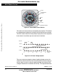
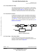
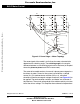
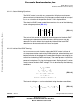
Figure 3-5. Power Stage — Motor Topology
The second goal of the model is to find how the motor characteristics
depend on the switching angle. The switching angle is the angular
difference between a real switching event and an ideal one (at the point
where the phase-to-phase back-EMF crosses zero).
The motor-drive model consists of a normal 3-phase power stage plus a
brushless dc motor. Power for the system is provided by a voltage
source (U
d
). Six semiconductor switches (S
A/B/C t/b
), controlled
elsewhere, allow the rectangular voltage waveforms (see Figure 3-2) to
be applied.
The semiconductor switches and diodes are simulated as
ideal devices. The natural voltage level of the whole model is put at one
half of the dc-bus voltage. This simplifies the mathematical expressions.
B
C
A
backEMF b
backEMF c
backEMF a
Rb
Ra Rc
Lb
Lc
u
u
uu
u
u
u
La
u
u
u
/2
d
=
+
-
u
/2
d
=
+
-
u
AB
I
Sa
I
d0
S
At
S
Bt
S
Ct
S
Ab
S
Bb
S
Cb
I
Sb
I
Sc
u
BC
u
CA
u
Sb
u
Sc
u
Sa
u
0
u
VC
u
VB
u
VA
O
Frees
cale Semiconductor,
I
Freescale Semiconductor, Inc.
For More Information On This Product,
Go to: www.freescale.com
nc...