
Personal Computer - Word Processor User Manual

BLDC Motor Control
Brushless DC Motor Control Theory
DRM028 — Rev 0 Designer Reference Manual
MOTOROLA BLDC Motor Control 27
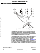
3.2.2 3-Phase BLDC Power Stage
The voltage for 3-phase BLDC motor is provided by a 3-phase power
stage controlled by digital signals. Its topology is the one as for the AC
induction motor (refer to Figure 3-5). The power stage is usually
controlled by a dedicated microcontroller with on-chip PWM module.
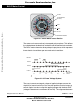
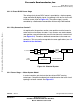
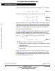
3.2.3 Why Sensorless Control?
As explained in the previous section, rotor position must be known in
order to drive a brushless dc motor. If any sensors are used to detect
rotor position, sensed information must be transferred to a control unit
(see Figure 3-4). Therefore, additional connections to the motor are
necessary. This may not be acceptable for some applications (see 1.3
Benefits of the Solution).
Figure 3-4. Classical System
3.2.4 Power Stage — Motor System Model
In order to explain and simulate the idea of back-EMF sensing
techniques a simplified mathematical model based on the basic circuit
topology has been created. See Figure 3-5.
AC LINE VOLTAGE
–
=
POWER STAGE
POSITION
SENSORS
LOAD
CONTROL UNIT
CONTROL SIGNALS
POSITION FEEDBACK
SPEED
SETTING
M
MOTOR DRIVE
Frees
cale Semiconductor,
I
Freescale Semiconductor, Inc.
For More Information On This Product,
Go to: www.freescale.com
nc...