
Personal Computer - Word Processor User Manual

BLDC Motor Control
Designer Reference Manual DRM028 — Rev 0
26 BLDC Motor Control MOTOROLA
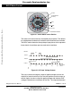
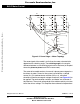
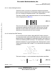
Figure 3-3. BLDC Motor Back EMF and Magnetic Flux
The filled areas in the tops of the phase back-EMF voltage waveforms
indicate the intervals where the particular phase power stage
commutations occur. The power switches are cyclically commutated
through the six steps; therefore, this technique is sometimes called six
step commutation control. The crossing points of the phase back-EMF
voltages represent the natural commutation points. In normal operation
the commutation is performed here. Some control techniques advance
the commutation by a defined angle in order to control the drive above
the pulse-width modulator (PWM) voltage control.
Ps i_ A
Ps i_ B
Ps i_ C
Ui_A
Ui_B
Ui_C
Ui_ AB
Ui_ BC
Ui_ CA
Atop Btop Ctop
Cbot Abot Bbot
Speed reversal
“Natural” commutation point
Phase Magnetic
Phase Back EMF
Phase-Phase
Flux Linkage
B–C
C–A
A–B
PH. A
PH. B
PH. C
Back EMF
PH. A
PH. B
PH. C
“NATURAL” COMMUTATION POINT
SPEED REVERSAL
ACTING POWER SWITCH IN THE POWER STAGE
Frees
cale Semiconductor,
I
Freescale Semiconductor, Inc.
For More Information On This Product,
Go to: www.freescale.com
nc...