
Personal Computer - Word Processor User Manual

User Guide
Tuning for Customer Motor
DRM028 — Rev 0 Designer Reference Manual
MOTOROLA User Guide 145
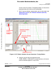
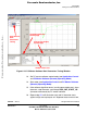
In the real system, the ZC-Cmt angle is a little bit greater than the
theoretical calculation. This is due to the response time of the hardware
back-EMF zero crossing sensing. Therefore, the default software setting
is COEF_HLFCMT =0.375
Normally, COEF_HLFCMT should only be changed if you need a
different commutation angle (time from back-EMF zero crossing to
commutation). For example, for motor field weakening.
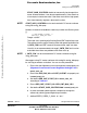
The relation between COEF_HLFCMT and the commutation can also be
defined by Advance_angle, which is the electrical angle shift from ideal
commutation.
(EQ 6-7.)
(EQ 6-8.)
Advance_angle = 15° for COEF_HLFCMT = 0.25
Advance_angle = 7.5° for COEF_HLFCMT = 0.375
Advance_angle = 0° for COEF_HLFCMT = 0.5
The relation between back-EMF zero crossing and the commutation is
explained in the section 3.3.1.3 Running — Commutation Time
Calculation.
6.5.5.2 Start-up Constants and Maximal Commutation Period
Constants defining start-up need to be changed according to the drive
dynamics.
Start Commutation Period [µs]:
/* MUST_CHANGE_8_EXPER: */
#define PER_CMT_START_US 4000.0
Range: <0,PER_CMT_MAX_US/2>
PER_CMT_START_US is the period used to calculate the first (start)
commutation period.
PER_CMT_START_US period must be changed for any motor
accommodation. It can be set experimentally. If the motor displays
errors during Starting (Back-EMF Acquisition) state, beginning
Advance_angle 30 Deg ZC-Cmt angle–=
COEF_HLFCMT
1
2
-
Advance_angle
60
-------------------------
–=
Frees
cale Semiconductor,
I
Freescale Semiconductor, Inc.
For More Information On This Product,
Go to: www.freescale.com
nc...