
Personal Computer - Word Processor User Manual

User Guide
Designer Reference Manual DRM028 — Rev 0
116 User Guide MOTOROLA
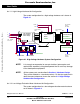
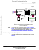
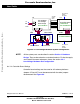
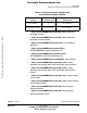
Figure 6-3. Low-Voltage Hardware System Configuration
NOTE: All the system parts are described in section Section 4. Hardware
Design. They can be ordered as a standard products. For the the supply
and in detail document references shown see section 4.2.3
Low-Voltage Hardware Set Configuration.
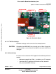
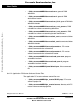
6.4.1.4 Controller Board Settings
Controller board settings are the same for all hardware platforms.
Jumpers JP3 and JP7 must be connected with the other jumpers
disconnected. See Figure 6-4.
+12
White
Black
SG40N
J13
GND
J5
ECMTRLOVBLDC
ECLOVACBLDC
Red
Controller Board
U2
EVM1
J5
Red
Not Connected
40w flat
ribbon
cable
J20
PC Computer
RS232 -
emulator
Black
U1
Motor-Brake
J19
KITMMDS08MR32
J16 J17 J18
SM40N
Not Connected
MB1
PC Computer
RS232 -
PC Master
White
ECCTR908MR32
HC908MR32
3ph AC/BLDC
Low Voltage
Power Stage
12VDC
Frees
cale Semiconductor,
I
Freescale Semiconductor, Inc.
For More Information On This Product,
Go to: www.freescale.com
nc...