
Personal Computer - Word Processor User Manual

User Guide
Designer Reference Manual DRM028 — Rev 0
114 User Guide MOTOROLA
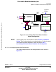
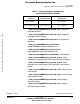
6.4.1.1 High-Voltage Hardware Set Configuration
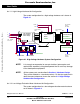
The system configuration for a high-voltage hardware set is shown in
Figure 6-1
Figure 6-1. High-Voltage Hardware System Configuration
NOTE: It is strongly recommended to use opto-isolation (optocouplers and
optoisolation amplifiers) during development time to avoid any damage
to the development equipment.
NOTE: All the system parts are described in Section 4. Hardware Design.
They can be ordered as a standard products. For the the supply and in
detail document references shown see section 4.2.1 High-Voltage
Hardware Set Configuration.
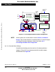
6.4.1.2 Low-Voltage Evaluation Motor Hardware Set Configuration
The system configuration for a low-voltage evaluation motor hardware
set is shown in Figure 6-2.
ECOPTHIVACBLDC
U1
U2 U3
EVM1
MB1
3ph AC/BLDC
High Voltage
Power Stage
PC Computer
RS232 -
PC Master
100 - 240VAC
ECCTR908MR32
J13.1 J13.2 J13.3
Red
Black
49 - 61 Hz
J5
SM40V
PC Computer
RS232 -
emulator
White
SG40N
40w flat ribbon
cable
L
J11.1
J11.2
N
J14 J1
Black
KITMMDS08MR32
Not Connected
PE
J5
Not Connected
+12VDC
J2
ECOPT
HC908MR32
GND
Optoisolation
Board
White
Controller Board
40w flat ribbon
cable
JP1.1 JP1.2
ECMTRHIVBLDC
Motor-Brake
Red
Frees
cale Semiconductor,
I
Freescale Semiconductor, Inc.
For More Information On This Product,
Go to: www.freescale.com
nc...