
Technical data


MC68HC912B32 MOTOROLA
MC68HC912B32TS/D 101
RX4XE — Receive 4X Enable
Reception of a BREAK symbol automatically clears this bit and sets the BSVR register to $1C.
0 = BDLC transmits and receives at 10.4 kbps
1 = BDLC is in 4X receive only operation
NBFS — Normalization Bit Format Select
Controls the format of the normalization bit.
0 = Normalization bit is a zero (0) when the response part of an in-frame response (IFR) does not
end with a CRC byte. Normalization bit is a one (1) when the response part of an in-frame re-
sponse (IFR) ends with a CRC byte.
1 = Normalization bit is a one (1) when the response part of an in-frame response (IFR) does not
end with a CRC byte. Normalization bit is a zero (0) when the response part of an in-frame re-
sponse (IFR) ends with a CRC byte.
TEOD — Transmit End of Data
Marks the end of a BDLC message by appending an 8-bit CRC after completing transmission of the
current byte. This bit is also used to end an IFR transmission.
0 = TEOD is automatically cleared at the rising edge of the first CRC bit or if an error is detected.
When TEOD is used to end an IFR transmission, TEOD is cleared when the BDLC receives
back a valid EOD symbol or an error condition occurs.
1 = Transmit EOD symbol
TSIFR, TMIFR1, TMIFR0 — Transmit In-Frame Response Control
Controls the type of in-frame response being sent. If more than one bit is set, the bits will be interpreted
according to Table 34 although the bits can be read back as they were set.
The BDLC supports the in-frame response (IFR) features of J1850. The four types of J1850 IFR are
shown below.
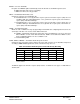
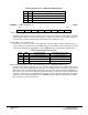
Table 34 Transmit In-Frame Response Control Bit Priority Encoding
Write/Read Internal Interpretation
TSIFR TMIFR1 TMIFR0 TSIFR TMIFR1 TMIFR0
000000
1
100
01
010
001001
Shaded cells indicate bits which do not affect internal interpretation. These bits will be read
back as written.