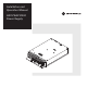
Installation and Operation Manual ID O V EN Y T K N O A R R B R L A EA W S IF GX2-PSAC10D-R Power Supply P 2- 0 pp -0 r Su 01 we -0 Po C 41D-R 00 88C10 00 0 52 SA 30 X G 0 66 P A 06 E ly E9 C 00 X0 669 USE ONLY WITH 250V FUSES M IN O 50/ PU DE L 60 T: 11 : Hz 5/2 G X 4.5 30V 2 -P /2.3 ~ A OU SAC TP 10 UT: D 1 -R 5.1 2V V P 1 RO 17.9 6.1A DUC AM MA TO AX X. 3 F PH . M .7V ILIP AX . PO 1 PINE WE 9.2A S R:3 M 00W AX .
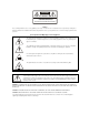
CAUTION RISK OF ELECTRIC SHOCK CAUTION: TO REDUCE THE RISK OF ELECTRIC SHOCK, DO NOT REMOVE COVER (OR BACK). NO USER-SERVICEABLE PARTS INSIDE. REFER SERVICING TO QUALIFIED SERVICE PERSONNEL. Caution These servicing instructions are for use by qualified personnel only. To reduce the risk of electrical shock, do not perform any servicing other than that contained in the Installation and Troubleshooting Instructions unless you are qualified to do so. Refer all servicing to qualified service personnel.
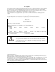
FCC Compliance This equipment has been tested and found to comply with the limits for a Class A digital device, pursuant to Part 15 of the FCC Rules. These limits are designed to provide reasonable protection against harmful interference when the equipment is operated in a commercial environment. This equipment generates, uses, and can radiate radio frequency energy and, if not installed and used in accordance with the Installation Manual, may cause harmful interference to radio communications.
Contents Section 1 Introduction Using This Manual ........................................................................................................................................................................... 1-2 Related Documentation................................................................................................................................................................... 1-2 Document Conventions............................................................................
ii Contents Figures Figure 1-1 GX2-PSAC10D-R............................................................................................................................................................1-1 Figure 2-1 GX2-HSG* fully populated .............................................................................................................................................2-1 Figure 2-2 GX2-PSAC10D-R front view..........................................................................................
Section 1 Introduction The OmniStar® GX2 is a fiber optic broadband transmission platform for headend and hub locations that supports advanced hybrid-fiber coax telecommunications systems. The GX2 series is a complete line of headend fiber optic products designed to transport video and data signals in CATV systems and related applications. The OmniStar GX2 system is flexible in its application and includes a series of modules and options that you can select to accommodate system requirements.
1-2 Introduction Using This Manual The following sections provide information and instructions to install the GX2-PSAC10D-R: Section 1 Introduction provides a product description, related documentation, the technical helpline, and repair/return information. Section 2 Overview provides an overview of the GX2 system and a functional description of the GX2-PSAC10D-R. Section 3 Installation and Operation provides instructions on how to install the GX2-PSAC10D-R and verify that it is operating properly.
Introduction 1-3 If You Need Help If you need assistance while working with the GX2-PSAC10D-R, contact the Motorola Technical Response Center (TRC): Toll-free: 1-888-944-HELP (1-888-944-4357) Outside the U.S.: 1-215-323-0044 Direct: 1-847-725-4011 Motorola Online: http://businessonline.motorola.com The TRC is on call 24 hours a day, 7 days a week. In addition, Motorola Online offers a searchable solutions database, technical documentation, and low-priority issue creation and tracking.
1-4 Introduction Calling for Repairs If repair is necessary, call Motorola’s Repair Facility at 1-800-227-0450 for a Return for Service Authorization (RSA) number before sending the unit. The RSA number must be prominently displayed on all equipment cartons. The Repair Facility is open from 8:00 AM to 5:00 PM Central Time, Monday through Friday.. When calling from outside the United States, use the appropriate international access code, and then call 956-541-0600 to contact the Repair Facility.
Section 2 Overview The OmniStar GX2 platform provides increased rack density, reliability, ease of operation, and computer-aided troubleshooting through the extensive use of status monitoring. Low time-to-repair is facilitated because application modules are accessible and replaceable from the front of the OmniStar GX2 equipment shelf. Fiber connections are also located in the front while RF and power connections are located on the rear of the equipment shelf.
2-2 Overview Figure 2-2 illustrates a front view of the GX2-PSAC10D-R: Figure 2-2 G X 2 - P S AC 1 0 D - R f r o n t vi ew Figure 2-3 illustrates a top view of the GX2-PSAC10D-R: Figure 2-3 G X 2 - P S AC 1 0 D - R t o p vi ew CAUTION Surface may be hot. Disconnect power and allow surface to cool before touching.
Overview 2-3 Figure 2-4 illustrates a rear view of the GX2-PSAC10D-R: Figure 2-4 G X 2 - P S AC 1 0 D - R r e a r vi ew IEC LED connector Thumbscrews Redundancy The unused compartment on the bottom of the GX2-HSG* can be used for redundant powering with the purchase of a second power supply. For redundancy, it is possible to use two GX2-PSAC10D-R's (as shown in Figure 3-1), two GX2-PSDC10Cs, or any combination of GX2-PS*10* power supplies.
Section 3 Installation and Operation This section provides instructions to install the GX2-PSAC10D-R power supply in the GX2-HSG* and verify its operation. Unpacking Unpack the GX2-PSAC10D-R and inspect it for damage. If damage is visible, set it aside in the original packing material and contact the Motorola Customer Service Department for further instructions. Record the model number, serial number, and related information for future reference.
3-2 Installation and Operation Powering After all connections, including fiber, have been established, apply power to the GX2-HSG*. Power connections are in the rear of the equipment shelf as illustrated in Figure 3-1.
Installation and Operation 3-3 Fault Reporting Each output voltage and the internal voltage of the supplies is monitored. The temperature of the incoming air, the heat sink, and fan operation are monitored as well. In the event of a fan failure, a major alarm is sent to the GX2-CM100B control module and the local LED glows red. The monitored signals are all compared to their appropriate internal specification.
Ap pen dix A Specifications Specifications for the GX2-PSAC10D-R are valid over the given operating temperature range. Refer to the current Motorola BCS product catalog for additional information not provided in this section. Input Power AC input voltage 105 Vrms to 264 Vrms AC current At 115 V At 230 V 4.0 amps rms maximum with full load 2.
Ap pen dix B Menus This appendix provides information about: Using the optional SDU with display to access GX2-PSAC10D-R menus The menu structure Alarms Table B-1 identifies the procedure for navigating through the GX2-PSAC10D-R menus using the optional SDU with display: Table B-1 G X 2 - P S AC 1 0 D - R m e n u s To Use Scroll to the top-level power supply menu Press the up or down arrows to scroll to the PS1 or PS2 menu.
B-2 Menus Module Info Menu ALIAS> User selected (default GX2-POWER SUPPLY) MODEL: GX2-PSAC10D-R S/N: 0123456789ABCDEF DATE CODE: mmddyyyy FW REV: XX HW REV: XX Alarms The second line on the SDU can display any of the following messages when an alarm condition exists: FAN CURRENT ALARM +12V BACKPLANE ALARM +5.1V BACKPLANE ALARM +3.
Abbreviations and Acronyms The abbreviations and acronyms list contains the full spelling of the short forms used in this manual: CATV Community Antenna Television dB decibels dBm decibels referenced to one milliwatt dBc decibels relative to carrier level dBmV decibels referenced to one millivolt ESD electrostatic discharge LED light-emitting diode MHz Megahertz mW milliwatts RF radio frequency RSA Return for Service Authorization TRC Technical Response Center TTR time-to-repair GX
Visit our website at: www.motorola.