
Computer Hardware User Manual

2-2
Hardware Preparation and Installation
2
Chapter 4, and/or in the MVME162FX Embedded Controller
Programmer's Reference Guide as listed in Related Documentation in
Chapter 1.)
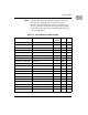
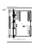
Figure 2-1 illustrates the placement of the switches, jumper
headers, connectors, and LED indicators on the MVME162LX.
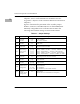
Manually configurable items on the board are listed in the
following table. Default settings are enclosed in brackets.
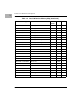
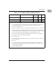
Table 2-1. Jumper Settings
Jumper Function Settings
J1
System
controller
selection
No jumper
[1-2]
2-3
Not system controller.
System controller.
Auto system controller.
J11
IP bus clock
selection
[1-2]
2-3
8MHz clock.
32MHz clock.
J12
SCSI
termination
No jumper
[1-2]
Onboard terminators disabled.
Onboard terminators enabled.
J14
SRAM backup
power source
selection
No jumper
[1-3, 2-4]
3-5, 4-6
1-3, 4-6
3-5, 2-4
Backup power disabled.
Primary : VMEbus +5V STBY Ñ secondary : VMEbus +5V STBY.
Primary : onboard battery Ñ secondary : onboard battery.
Primary : VMEbus +5V STBY Ñ secondary : onboard battery.
Primary : onboard battery Ñ secondary : VMEbus +5V STBY.
J16
Flash write
protection
[No jumper]
1-2
Flash write protection on (writes disabled).
Flash write protection off (writes enabled).
J18
IP bus strobe
selection
No jumper
[1-2]
Strobe disconnected.
Strobe connected.
J19
IP DMA snoop
selection
1-2, no jumper
[1-2, 3-4]
Snoop enabled (pins 1-2 = donÕt care).
Snoop inhibited.
J20
EPROM/Flash
conÞguration
3-4, 9-11, 10-12
[5-6, 9-11, 8-10]
7-9, 8-10
1-2, 7-9, 8-10
256K x 8 EPROMs.
512K x 8 EPROMs.
1M x 8 EPROMs.
1M x 8 EPROMs (on-board Flash disabled).
J21
General-
purpose
readable jumper
conÞguration
[No jumper]
7-8
EPROM selected.
Flash selected.
Other headers are user-deÞnable (see description).