
Stereo System User Manual


A - 324 DSP96002 USER’S MANUAL MOTOROLA
If there are wait states, (i.e., assumption 4 is not applicable) then to each 1-word instruction timing a "+ap"
term should be added and to each 2-word instruction a "+(2 * ap)" term should be added to account for the
program memory wait states spent to fetch an instruction word to fill the pipeline.
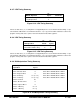
A.9.10 Jump Instructions Timing Summary
+ jx
Jump Instruction Operation Cycles
Jbit I/O Short aio + (2 * ap)
Jbit Absolute Short 2 * ap
Jbit Register Direct 2 * ap
Jbit X Memory ea + ax + (2 * ap)
Jbit Y Memory ea + ay + (2 * ap)
Jxxx ea + (2 * ap)
where Jbit = JCLR, JSCLR, JSET, JSSET, BRCLR, BSCLR,
BRSET and BSSET
Jxxx = Jcc, JMP, JScc, JSR, Bcc, BRA, BScc and BSR
Figure A-17 Jump Instruction Timing Summary
The "ea" term in the Jbit equations refers only to the clock cycles spent in X and Y Data memory accesses
to obtain the bit to be tested. The "ea" term in the Jxxx equation refers only to the clock cycles spent while
calculating the jump target address.
All one-word jump instructions execute TWO program memory fetches to refill the pipeline and this is rep-
resented by the "+(2 * ap)" term.
All two-word jumps execute THREE program memory fetches to refill the pipeline but one of those fetches
is sequential (the instruction word located at the jump instruction 2nd word address+1),and so it is not
counted as per assumption 4. If the jump instruction was fetched from a program memory segment with
wait states, another "ap" should be added to account for that third fetch.
A.9.11 RTI/RTR/RTS Timing Summary
Operation + rx cycles
RTI 2 * ap
RTR 2 * ap
RTS 2 * ap
Figure A-18 RTI/RTR/RTS Timing Summary