
user manual


66 MTM5400 Mobile Terminal Installation Manual INSTALLATION
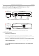
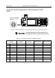
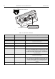
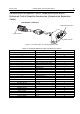
Figure 29 View of the Enhanced Control Head’s rear connectors
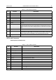
Table 14 10-Pin Telco Connector
Telco Connector Pin Function Description
1 AUDIO + Balanced Audio + (Bidirectional)
2 NC Not Connected
3 BUS + This is used for communication between the radio and an
Enhanced Control Head.
4 AUDIO - Balanced Audio - (Bidirectional)
5 NC Not Connected
6 GND Ground
7 Radio On/Off Control This is the Enhanced Control Head service request input.
A level of 5 volts indicates that the Enhanced Control Head
needs to communicate with the radio. In addition it
switches on the radio's voltage regulators. The idle state is
a level below 0.6V.
8 SCI_TX This if for communication between the radio and the
Enhanced Control Head.
9 FLT_A + This voltage is at battery voltage level and is available as
long as the radio is connected to the supply voltage. The
maximum current is 300mA. A fuse in the radio prevents
further circuit damage in case of shorting this pin to
ground.
10 Analog Ground Analog Ground
1
13
110
14
25
10-Pin Telco Connector
25-Pi n Back Connector