
user manual

INSTALLATION MTM5400 Mobile Terminal Installation Manual 55
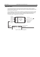
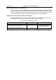
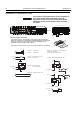
Connection Plan for the Alarm Relay
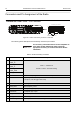
Connection Plan for the Emergency Switch
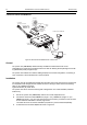
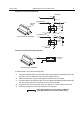
To install the cable, carry out the following steps.
1. Connect the stripped lead of the fuse holder cable only to an ignition switched terminal of the
fuse block. Use the supplied terminal or any other suitable terminal.
2. Mount the fuse holder using the mounting hole, and dress wires as required.
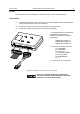
3. Cut the thin cable to the required length, crimp the supplied red lead to the stripped lead of the
thin cable, and connect it to the blue terminal of the fuse holder cable.
4. Connect the other end of the ignition sense thin cable to pin 4 of the junction box terminal.
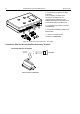
5. Insert the provided fuse into the fuse holder and close the cover.
PIN 4: If the ignition line is not used, it needs to be
grounded. Interference can cause radio to hang.
5
5
ALTERNATIVE
ALTERNATIVE
BLK
BLK
86
87
85 30
RED
RED
BLK
ALARM
RELAY
+12 V
ALARM
RELAY
86
87
85 30
RED
+12 V
BLK
5
BLK
RED +12V
BUZZER
+12 V
JUNCTION BOX TERMINAL
+12 V
RED
+12 V
External
alarm
1
2
3
4
5
6
7
EMERGENCY
SWITCH
JUNCTION BOX TERMINAL
1
2
3
4
5
6
7