
user manual

INSTALLATION MTM5400 Mobile Terminal Installation Manual 53
Service
The junction box PCB is not repairable. Please order a new junction box as necessary.
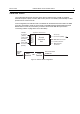
Connections
1. Connect all accessories to the junction box. If it is required please see “Re-crimp Procedure”
on page 61to be able to connect your accessory.
2. Connect the mobile-terminal-to-Junction box cable to the junction box.
3. Connect the programming cable to the junction box (if required).
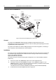
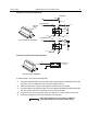
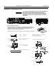
Figure 23 Connectors on the Junction Box - Front Panel
PIN 4: Use an adapter between the radio and the
accessory connector to short the ignition to ground.
Interference can cause radio to hang.
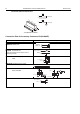
1
2
3
7
7
6
5
4
3
2
1
6
5
4
3
2
1
1
2
3
4
5
6
7
1 = Connecting cable from Junction Box
to MTM5400 (rear side 26-pin
accessory connector) for installation
purpose only.
PMKN4101A (length 6 m)
PMKN4102A (length 4 m)
PMKN4103A (length 2 m)
2 = Connector for accessory terminal
pin 1 SPEAKER +
pin 2 SPEAKER -
pin 3 EXT_PTT
pin 4 IGNITION SENSE
pin 5 EXT_ALARM
pin 6 EMERGENCY
pin 7
3 = Connector for visor microphone