
user manual


4
PrPMC800/800ET Processor PMC Module Installation and Use (PrPMC800A/IH5)
29
4 Connector Pin Assignments
Introduction
This chapter provides connector pin assignments for all connectors on the PrPMC800/800ET
board.
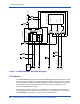
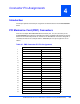
PCI Mezzanine Card (PMC) Connectors
There are four 64-pin EIA E700 AAAB SMT connectors (P11, P12, P13, and P14) on the
PrPMC800/800ET that provide the 32/64-bit PCI interface and optional I/O interface to the host
board. The P14 connector provides an interface to the bank B flash and I
2
C bus along with a
secondary interface to the serial port and the JTAG/COP port. The pin assignments are as
follows.
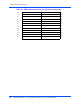
Table 4-1. PMC Connector P11 Pin Assignments
P11
1 TCK -12V (No Connect) 2
3GND INTA# 4
5INTB# INTC# 6
7 PRESENT# +5V (No Connect) 8
9 INTD# No Connect 10
11 GND No Connect 12
13 CLK GND 14
15 GND GNT# 16
17 REQ# +5V (No Connect) 18
19 VIO AD31 20
21 AD28 AD27 22
23 AD25 GND 24
25 GND C/BE3# 26
27 AD22 AD21 28
29 AD19 +5V (No Connect) 30
31 VIO AD17 32
33 FRAME# GND 34
35 GND IRDY# 36
37 DEVSEL# +5V (No Connect) 38
39 GND LOCK# 40