
user manual


PrPMC800/800ET Processor PMC Module Installation and Use (PrPMC800A/IH5)
3 Functional Description
24
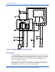
Figure 3-2. PrPMC800/800ET Reset Block Diagram
PCI Interface
The PrPMC800/800ET module contains four EIA-E700 AAAB connectors that provide a 32/64-
bit PCI interface to an IEEE P1386.1 PMC compliant baseboard. Connectors P11-P13 provide
the 32/64-bit 66 MHz capable PCI interface while P14 provides an I/O path from the module to
the baseboard. Signals routed to P14 include the I
2
C bus, the RS-232 debug port, the
processor JTAG/COP and the Xport 1.
PCI bus pullup resistors required by the PCI Revision 2.1 Specification (for motherboards),
including 64-bit expansion signals, must be supplied by the baseboard. This is required if the
PrPMC800/800ET is operating as a monarch or non-monarch module.
Power Up
Reset
Harrier ASIC
PURST_L
MPC750-Class Processor
TRST_L
J1-17
DEBUGRST_L
P12-13
PCIRST_L
HRESET_L
J1-4
RWCPUTSRT_L
J1-13
RWCPURST_L
RST_L
WDT1TO_L
HRST0_L
P12-60
RSTOUT_L
(140ms)
P14-14
P14-7
SRST0_L
SRESET_L
J1-11
RWSRESEST_L
P14-13
AUXRST_L
RSTSW_L
ABTSW_L
ABORT_L
J1-18
P14-42
RESETOUT_L
MCSR.RSTOUT
REQ64 LOGIC