
user manual


3 Functional Description
PrPMC800/800ET Processor PMC Module Installation and Use (PrPMC800A/IH5)
23
PrPMC800/800ET Power Supplies
The PrPMC800/800ET module requires only a +3.3V input voltage. The processor core voltage
and the Harrier core voltage are generated on the module from the +3.3V input using the
LTC1702 dual synchronous switching regulator. In addition to the Harrier core voltage, the
+2.5V supply provides the processor, Harrier, and L2 cache I/O voltages.
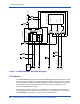
Module Reset Logic
A block diagram of the PrPMC800/800ET module reset logic appears in Figure 3-2 on page 24.
There are five standard sources of reset on the PrPMC800/800ET. They are:
1. Power-Up reset
2. PMC PCI RST#
3. Watchdog Timer reset via the Harrier Watchdog 1 Timer output
4. Software generated module reset from Harrier RSTOUT control bit
5. Debug RESET_L signal from debug header
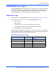
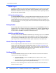
The following table describes the function of each reset source. A module reset includes the
processor, Harrier and Ethernet. The RESETOUT_L pin must be tied into the baseboard reset
logic, which drives PCIRST# in order to produce module reset.
Table 3-4. Reset Source Functions
Reset Source Type Module Reset PrPMC RESETOUT_L
Active
Power-Up Reset x x
PMC PCI RST# x
WDT1 Timer Output x
SW Reset x
Debug Reset x