
Microcontroller User's Manual


24-2 MCF5282 User’s Manual MOTOROLA
Interface Features
• Acknowledge bit generation/detection
• Bus-busy detection
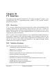
Figure 24-1 is a block diagram of the I
2
C module.
Figure 24-1. I
2
C Module Block Diagram
Figure 24-1 shows the relationships of the I
2
C registers, listed below:
•I
2
C address register (I2ADR)
•I
2
C frequency divider register (I2FDR)
•I
2
C control register (I2CR)
•I
2
C status register (I2SR)
I
2
C data I/O register (I2DR)These registers are described in Section 24.5, “Programming
Model.”
Address
Compare
In/Out
Data
Shift
Start, Stop,
Input
Sync
Clock
Control
Registers and ColdFire Interface
Address Decode
I
2
C Address
Data MUX
SDASCL
AddressIRQ Data
and
Arbitration
Control
Register
Internal Bus
Register
(IADR)
I
2
C Frequency
Divider Register
(IFDR)
I
2
C Data
I/O Register
(I2DR)
I
2
C Status
Register
(I2SR)
I
2
C Control
Register
(I2CR)