
Microcontroller User's Manual


8-8 MCF5282 User’s Manual MOTOROLA
Register Descriptions
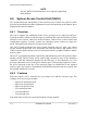
765 32 1 0
Field CWE CWRI CWT[2:0] CWTA CWTAVAL CWTIC
Reset 0000_0000
R/W R/W
Address IPSBAR + 0x011
Figure 8-4. Core Watchdog Control Register (CWCR)
Table 8-5. CWCR Field Description
Bits Name Description
7 CWE Core watchdog enable.
0 SWT disabled.
1 SWT enabled.
6 CWRI Core watchdog reset/interrupt select.
0 If a time-out occurs, the CWT generates an interrupt to the processor core. The interrupt level for
the CWT is programmed in the interrupt control register 7 (ICR7) of INTC0.
1 A CWT time-out generates a soft reset to the entire device.
5–3 CWT[2:0] Core watchdog timing delay. These bits select the timeout period for the CWT as shown in Table 8-6.
At system reset, the CWT field is cleared signaling the minimum time-out period but the watchdog is
disabled (CWCR[CWE] = 0).
2 CWTA Core watchdog transfer acknowledge enable.
0 CWTA Transfer acknowledge disabled.
1 CWTA Transfer Acknowledge enabled. After one CWT time-out period of the unacknowledged
assertion of the CWT interrupt, the transfer acknowledge asserts, which allows CWT to terminate
a bus cycle and allow the interrupt acknowledge to occur.
1 CWTAVAL Core watchdog transfer acknowledge valid.
0 CWTA Transfer Acknowledge has not occurred.
1 CWTA Transfer Acknowledge has occurred. Write a 1 to clear this flag bit.
0 CWTIF Core watchdog timer interrupt flag.
0 CWT interrupt has not occurred
1 CWT interrupt has occurred. Write a 1 to clear the interrupt request.
Table 8-6. Core Watchdog Timer Delay
CWT [2:0] CWT Time-Out Period
000 2
9
Bus clock frequency
001 2
11
Bus clock frequency
010 2
13
Bus clock frequency
011 2
15
Bus clock frequency
100 2
19
Bus clock frequency
101 2
23
Bus clock frequency
110 2
27
Bus clock frequency
111 2
31
Bus clock frequency