
Development Board User's Manual


12
PORTS AND CONNECTORS
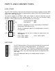
LCD_PORT
The LCD_PORT interface is connected to the data bus and memory mapped to locations BF0
– BFF hex assigned to CS7. For the standard display, address BF0 is the Command register,
address BF1 is the Data register.
The interface supports all OPTREX DMC series displays in 8 bit bus mode with up to 80
characters and provides the most common pinout for a dual row rear mounted display
connector. Power, ground, and Vee are also available at this connector.
+5V 2 1 GND
A0 4 3 LCD-Vee
LCD1 6 5 /RW
D9 8 7 D8
D11 10 9 D10
D13 12 11 D12
D15 14 13 D14
Command Register: $BF0
Data Register: $BF1
LCD-Vee is supplied by U13 and is adjusted by the CONTRAST
Potentiometer (adjustable resistor).
See the file KLCD12D6.ASM for an example program using this
LCD connector.
J3
LCD3
2 1
LCD2
4 3
LCD4
Additional lines can be used as enables for larger panels and
are mapped as:
LCD2 = $BF4 & $BF5 LCD4 = $BFC & $BFD
LCD3 = $BF8 & $BF9
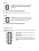
KEYPAD
1
PH0
2
PH1
3
PH2
4
PH3
5
PH4
6
PH5
7
PH6
8
PH7
The KEYPAD connector is a passive 8-pin connector that can be used to
connect a 4 x 4 matrix (16 key) keypad device. The connector is
mapped to HC12 I/O port H. This interface is implemented as a software
keyscan. Pins PH0-3 are used as column drivers which are active high
outputs. Pins PH4-7 are used for row input and will read high when their
row is high.
See the file KLCD12D6.ASM for an example program using this
connector.