CME-12D60 Development Board for Motorola 68HC912D60 Microcontroller xiom anufacturing 2000 2813 Industrial Ln. • Garland, TX 75041 • (972) 926-9303 FAX (972) 926-6063 email: Gary@axman.com • web: http://www.axman.
CONTENTS GETTING STARTED ............................................................................................3 Installing the Software..................................................................... 3 Board Startup .................................................................................. 3 Support Software ............................................................................ 4 Software Development .................................................................... 4 TUTORIAL...
GETTING STARTED The Axiom CME-12D60 single board computer is a fully assembled, fully functional development system for the Motorola 68HC912D60 microcontroller, complete with wall plug power supply and serial cable. Support software for this development board is provided for Windows 95/98 and NT operating systems. Follow the steps in this section to get started quickly and verify everything is working correctly. Installing the Software 1. Insert the Axiom 68HC12 support CD in your PC.
Support Software There are many useful programs and documents on the included HC12 support CD that can make developing projects on the CME-12D60 easier. You should browse the disk and copy anything you want to your hard drive. The flash programming utility (AxIDE) communicates with the board via its COM1 port and the supplied cable.
TUTORIAL This section was written to help you get started developing software with the CME-12D60 board. Be sure to read the rest of this manual as well as the documentation on the disk if you need further information. The following sections take you through the complete development cycle of a simple "hello world" program, which sends the string "Hello World" to the serial port.
Assembling source code An example program called “HELLO.ASM” is provided under the \EXAMPLES\D60 directory of the CD and if you installed AxIDE, under that programs \EXAMPLE\HC12D60 directory. You can assemble your source code using command line tools under a DOS prompt by typing: AS12 HELLO.ASM –LHELLO Most compilers and assemblers allow many command line options so using a MAKE utility or batch file is recommended if you use this method.
Running your application After creating a Motorola S-Record file you can "upload" it to the development board for a test run. The provided example “HELLO.ASM” was created to run from RAM so you can use the Mon12 Monitor to test it without programming it into Flash. If you haven’t done so already, verify that the CME-12D60 board is connected and operating properly by following the steps under “GETTING STARTED” until you see the Mon12 prompt, then follow these steps to run your program: 1.
Programming Flash EEPROM After debugging, you can program your application into Flash Memory so it executes automatically when you apply power to the board as follows: 1. Make a backup copy of HELLO.ASM then use a text editor to modify it. Remove the comment ; character before the following line to initialize the stack pointer which is necessary when running outside of a debugger: LDS #$7FE ; initialize the stack pointer 2.
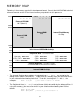
MEMORY MAP Following is the memory map for this development board. Consult the 68HC912D60 technical reference manual on the CD for internal memory map details for this processor.
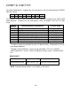
CONFIG SWITCH The CME-12D60 board is shipped from the manufacturer with the following default CONFIG SWITCH settings: 1 ON 2 ON 3 ON 4 ON 5 OFF 6 ON 7 OFF 8 OFF The 8 position CONFIG SWITCH provides an easy method of configuring the CME-12D60 board operation.
JUMPERS MON-SEL JUMPER Selects which firmware monitor in External EPROM (U6/7) the board will execute upon reset in expanded mode with monitor enabled by CONFIG SWITCH position 4. ON OFF Mon12 Debug Monitor Third party firmware support (NoICE, Metrowerks, etc.) PG_PULL / PH_PULL JUMPERS Pull up or Pull down I/O line bias resistor option jumpers. When port G or Port H are configured as inputs these options select which way the internal pull resistor’s operate.
PORTS AND CONNECTORS LCD_PORT The LCD_PORT interface is connected to the data bus and memory mapped to locations BF0 – BFF hex assigned to CS7. For the standard display, address BF0 is the Command register, address BF1 is the Data register. The interface supports all OPTREX DMC series displays in 8 bit bus mode with up to 80 characters and provides the most common pinout for a dual row rear mounted display connector. Power, ground, and Vee are also available at this connector.
MCU_PORT The MCU_PORT provides access to the peripheral features and I/O lines of the HC12 as follows: D0 D2 D4 D6 /XIRQ, PE0 VFP PG6 PG4 PG2 PG0 PH6 PH4 PH2 PH0 PS0 / RXD0 PS2 / RXD1 PS4 PS6 PCAN6 PCAN4 PCAN2 PCAN0 PT0 PT2 PT4 PT6 PP6 PP4 PP2 PP0 1 3 5 7 9 11 13 15 17 19 21 23 25 27 29 31 33 35 37 39 41 43 45 47 49 51 53 55 57 59 2 4 6 8 10 12 14 16 18 20 22 24 26 28 30 32 34 36 38 40 42 44 46 48 50 52 54 56 58 60 D1 D3 D5 D7 /DBE, PE7 /LSTRB PG7 PG5 PG3 PG1 PH7 PH5 PH3 PH1 PS1 / TXD0 PS3 / TXD1 PS5 PS
COM1 1 TXD0 2 RXD0 3 4 GND 5 The COM-1 port has a Female DB9 connector that interfaces to the HC12 internal SCI0 serial port. It uses a simple 2 wire asynchronous serial interface and is translated to RS232 signaling levels. 6 7 8 9 Pins 1, 4, and 6 are connected for default handshake standards. Pins 7 and 8 are connected for default handshake standards. Handshake pins can be easily isolated and connected to I/O ports if necessary.
BUS_PORT The BUS_PORT supports off-board memory devices as follows: GND D10 D9 D8 A0 A1 A10 / OE A11 A9 A8 A12 / WE CS1 CS3 CS5 +5V /RW E GND 1 3 5 7 9 11 13 15 17 19 21 23 25 27 29 31 33 35 37 39 D11 D12 D13 D14 D15 A2 A3 A4 A5 A6 A7 A13 CS0 CS2 CS4 IRQ /P-SEL CS6 CS7 / RESET 2 4 6 8 10 12 14 16 18 20 22 24 26 28 30 32 34 36 38 40 D8 - D15 High Byte Data Bus in Wide Expanded Mode and Peripheral 8 bit data bus. Port A in Single Chip Mode. A0 – A15 Memory Addresses 0 to 15.
TROUBLESHOOTING The CME-12D60 board is fully tested and operational before shipping. If it fails to function properly, inspect the board for obvious physical damage first. Ensure that all IC devices in sockets are properly seated. Verify the communications setup as described under GETTING STARTED and see the Tips and Suggestions sections following for more information. The most common problems are improperly configured communications parameters, and attempting to use the wrong COM port. 1.
Tips and Suggestions Following are a number of tips, suggestions and answers to common questions that will solve many problems users have with the CME-12D60 development system. You can download the latest software from the Support section of our web page at: www.axman.com Utilities • If you’re trying to program memory or start the utilities, make sure all jumpers and CONFIG SWITCH settings are correct.
TABLES TABLE 1. LCD Command Codes Command codes are used for LCD setup and control of character and cursor position. All command codes are written to LCD panel address $B5F0. The BUSY flag (bit 7) should be tested before any command updates to verify that any previous command is completed. A read of the command address $B5F0 will return the BUSY flag status and the current display character location address.
TABLE 3. Mon12 Monitor Commands BF [] BR [] BULK CALL [] G [] HELP LOAD [] MD [] MM or <=> <^> or <-> <.