
User guide


Designing Your Canopy Network March 2005
Through Software Release 6.1
Issue 1 Page 109 of 425
Canopy System User Guide
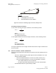
Transmitter
or Amplifier
receiver
transmitter
Fresnel zone
Figure 39: Fresnel zone
FresnelZoneCalcPage.xls
calculates the Fresnel zone clearance that is required between
the visual line of sight and the top of an obstruction that would protrude into the link path.
Non-Line of Sight (NLOS) Link
The Canopy 900-MHz modules have a line of sight (LOS) range of 40 miles (more than
64 km) and greater non-line of sight (NLOS) range than Canopy modules of other
frequency bands. NLOS range depends on RF considerations such as foliage,
topography, obstructions.
12.4.4 Finding the Expected Coverage Area
The transmitted beam in the vertical dimension covers more area beyond than in front of
the beam center. BeamwidthRadiiCalcPage.xls
calculates the radii of the beam coverage
area.
12.4.5 Clearing the Radio Horizon
Because the surface of the earth is curved, higher module elevations are required for
greater link distances. This effect can be critical to link connectivity in link spans that are
greater than 8 miles (12 km). AntennaElevationCalcPage.xls
calculates the minimum
antenna elevation for these cases, presuming no landscape elevation difference from one
end of the link to the other.
12.4.6 Calculating the Aim Angles
The appropriate angle of AP downward tilt is derived from both the distance between
transmitter and receiver and the difference in their elevations. DowntiltCalcPage.xls
calculates this angle.
The proper angle of tilt can be calculated as a factor of both the difference in elevation
and the distance that the link spans. Even in this case, a plumb line and a protractor can
be helpful to ensure the proper tilt. This tilt is typically minimal.
The number of degrees to offset (from vertical) the mounting hardware leg of the support
tube is equal to the angle of elevation from the lower module to the higher module (<B in
the example provided in Figure 40).