
Technical information


Audio Interface
34 G30 - Module Hardware Description December 15, 2009
Important: When implementing a single ended speaker design, it is required to place a series
capacitor and resistor on the speaker output line, as illustrated in Figure 2-18.
The capacitor should be of low tolerance with values of C = 10-22 uF.
The resistor value depends on the speaker application:
- For a handset device, the resistor value should be R = 0
Ω at the design stage, but
may be changed to a different value during audio safety testing, in case speaker
level limitation is required.
- For a headset device, safety regulations require the resistors value to be R >
2R
L
Ω,
where R
L
is the speaker impedance (e.g. 32Ω).
For example, when using a 32Ω speaker the series resistance would be R > 64Ω.
Mono Speaker (Headset) Port
The mono speaker port can be used for voice calls and DTMF tones. It is located at pin 47 on the
G30 81 pin LGA interface, named HDST_SPK.
It is designed as a single-ended output with 32
Ω impedance, referenced to the G30 analog ground.
Figure 2-19 shows the headset speaker circuit and Table 2-12 gives the headset speaker
specifications.
Figure 2-19: Mono Speaker (Headset) Circuit
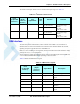
Table 2-11:
Speaker Port Specifications
Parameter Conditions Min Typ Max Unit
Output
Voltage
No load
Single ended
2.7 V
PP
Gain Programmable in
3 dB steps
-15 +9 dB
AC Output
Impedance
8 Ω
DC Voltage VCC/2 V
THD 8 Ω load
300 Hz - 4 kHz
1%
Isolation Speech, f> 4 kHz 60 dB