
Technical information


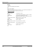


Table Of Contents
- Table of Contents
- List of Figures
- List of Tables
- Preface
- Manual Scope
- Target Audience
- Manual Organization
- Applicable Documents
- Contact Us
- Text Conventions
- Manual Banner Definitions
- Field Service
- General Safety
- Caring for the Environment
- Limitation of Liability
- Warranty Notification
- How to Get Warranty Service?
- Claiming
- Conditions
- What is Not Covered by the Warranty
- Installed Data
- Out of Warranty Repairs
- Revision History
- Chapter 1: Product Features
- Chapter 2: Introduction to AT Commands
- Chapter 3: AT Commands Reference
- Modem ID
- Subscriber Unit Identity
- +CGMI, +GMI, +FMI, Request Manufacturer ID
- +CGMM, +GMM, +FMM, Request Model ID
- +CGMR, +GMR, +FMR, Request Revision
- +CGSN, +GSN, Request Product Serial Number Identification
- +CSCS, Select Terminal Character Set
- +CIMI, Request IMSI
- +CFSN, Read Factory Serial Number
- I, Request Identification Information
- +CNUM, Request MSISDN(s)
- $, List of All Available AT Commands
- +CLAC, List of All Available AT Commands
- Capability Reporting
- Subscriber Unit Identity
- Call Control
- Managing a CSD (Data) Call
- Receiving a Data Call
- Call Control AT Commands
- D, Dial Command
- D>, Direct Dialing from Phone Books
- DL, Dial Last Number
- H, Hang-up Call
- A, Answer Incoming Call
- +CRC, Cellular Result Codes and RING, +CRING - Incoming Call Indication
- +CLIP, Calling Line Identification
- +CCWA, Call Waiting Command
- +CHLD, Call Related Supplementary Services Command
- +CCFC, Call Forwarding Number and Conditions
- +CLIR, Calling Line Identification Restriction
- +CBST, Select Bearer Service Type
- O, Return to Online Data State
- &Q, Asynchronous Mode
- +CHUP, Hang Up Call
- +CSNS, Single Numbering Call Scheme
- +MDC, Selection of Desired Message to Be Displayed Upon Connection of a Voice Call
- +CTFR1, Divert an Incoming Call When User Busy
- +MFIC, Filtering Incomming Calls
- +MVC, Motorola Vocoders Configuration
- Call Status Messages
- Call Advice of Charge Commands
- Supplementary Services
- Phone Books and Clock
- SMS
- SMS Commands
- +CSMS, Select Message Service.
- +CPMS, Preferred Message Storage
- +CMGF, Message Format
- +CSCA, Service Center Address
- +CSMP, Set Text Mode Parameters
- +CSDH, Show Text Mode Parameters
- +CNMI, New Message Indications to Terminal
- +CNMA, New Message Acknowledgment
- +CMTI, Unsolicited Response (New SMS-DELIVER Receipt Indication)
- +CMT, Unsolicited Response (New SMS-DELIVER Receipt)
- +CBM, Unsolicited Response (New CB Message Receipt)
- +CDSI, Unsolicited Response (New SMS-STATUS-REPORT Indication)
- +CDS, Unsolicited Response (New SMS-STATUS-REPORT Receipt)
- +CMGL, +MMGL, List Messages
- +CMGR, +MMGR, Read Message
- +MMAR, Motorola Mark As Read
- +CMSS, Send Message From Storage
- +CMGW, Write Message to Memory
- +CMGD, Delete Message
- +CGSMS, Select Service for MO SMS Messages
- +CMGS, Send SM to Network
- +CSCB, Cell Broadcast Messages
- +MCSAT, Motorola Control SMS Alert Tone
- +MEGA, Email Gateway Address
- +TSMSRET, Control SMS Sending Retry
- DCS handling
- SMS Commands
- Network
- Hardware Information
- Hardware Information Commands
- +CBC, Battery Charger Connection
- +CBAUD, Baud Rate Regulation
- +IPR, Local Terminal/G24 Serial Port Rate
- +GCAP, Request Overall Capabilities
- +MTDTR, DTR Line Test Command
- +MTCTS, CTS Line Test Command
- &K, RTS/CTS Flow Control
- &C, Circuit 109 Behavior
- &D, Circuit 108 Behavior
- +MCWAKE, GPRS Coverage
- +MGGIND, GSM/GPRS Service Indicator
- +CFUN, Shut Down Phone Functionality
- +ICF, DTE-DCE Character Framing
- ATS97, Antenna Diagnostic
- +MRST, Perform Hard Reset
- +TWUS, Wakeup Reason Set
- +TWUR, Wakeup Reason Request
- +TASW, Antenna Switch
- +TADIAG, Query Antennas ADC Value
- READY, Unsolicited Notification (UART Ready Indication)
- +MPSU, Motorola Physical Second Uart
- +MIOC, Motorola I/O Configure
- +MIOD, Motorola I/O Define
- +MMAD, Query and Monitor ADC Value
- +MPCMC, Continuous PCM Clock
- +MVREF, Motorola Voltage Reference
- Hardware Information Commands
- Audio
- Access
- Access Control Commands
- A/, Repeat Last Command
- AT, Check AT Communication
- +CPIN, Enter PIN for Unlocking SIM Card or Enter PUK for Unblocking SIM Card
- +EPIN, Enter SIM PIN2 to Verify PIN2 Indicator
- +TPIN, Query Number of Remaining SIM PIN/PUK Entering Attempts
- +CPWD, Change Password
- +CLCK, Facility Lock
- +EMPC, Unlocking or Locking Subsidy Code
- Access Control Commands
- Modem Configuration and Profile
- Modem Register Commands
- V, G24 Response Format
- Q, Result Code Suppression
- E, Command Echo
- X, Result Code Selection and Call Progress Monitoring Control
- S, Bit Map Registers
- \S, Show the Status of the Commands and S-registers in Effect
- \G, Software Control
- \J, Terminal Auto Rate
- \N, Link Type
- +CBAND, Change Radio Band
- ?, Return the Value of the Last Updated S-register
- &F, Set to Factory Defined Configuration
- Z, Reset to Default Configuration
- Sleep Mode Commands
- Error Handling Commands
- Modem Register Commands
- UI (User Interface)
- GPRS/EDGE
- GPRS Functionality
- GPRS Commands
- +CGCLASS, GPRS Mobile Station Class
- +CGDCONT, Define PDP Context
- +CGQMIN, Quality of Service Profile (Min Acceptable)
- +CGQREQ, Quality of Service Profile (Requested)
- +CGATT, GPRS Attach or Detach
- D*99, Request GPRS Service "D"
- +CGPRS, GPRS Coverage
- +CGACT, PDP Context Activate or Deactivate
- CGPADDR, GPRS ADDResses
- EDGE Commands
- TCP/IP
- +MIPCALL, Create a Wireless Link
- +MIPOPEN, Open a Socket (UDP or TCP)
- +MIPODM, Open a Socket (UDP or TCP) in Online Data Mode
- +MIPCLOSE, Close a Socket
- +MIPSETS, Set Size for Automatic Push
- +MIPSEND, Send Data
- +MIPPUSH, Push Data into Protocol Stack
- +MIPFLUSH, Flush Data from Buffers
- +MIPRUDP, Receive Data from UDP Protocol Stack
- +MIPRTCP, Receive Data from TCP Protocol Stack
- +MIPSTAT, Status Report
- +MIPDATA, Network Incoming Data Unsolicited Indication in Pseudo-command Mode
- MIPXOFF, Flow Control - Xoff
- MIPXON, Flow Control - Xon
- MIPCONF - Configure Internal TCP/IP stack
- +MPING, Start Ping Execution (ICMP Protocol)
- +MPINGSTAT, Status Update for +MPING Execution
- +MSDNS, Set DNS IP Address
- NOP - Compatible
- Fax Class 1
- RS232 Multiplexer Feature
- Modem ID
- Chapter 4: Using the Commands
- Setting Up the G24 (Power On and Initial Actions)
- Recommended G24 Initialization after Powerup
- SMS
- Managing Stored Messages in the G24 Memory
- Setting the Notification Indication for Incoming Messages (Using AT+CNMI)
- Another Possible Option for Setting the CNMI Notification Indication
- Setting TEXT Mode Parameters (Using AT+CMGW and AT+CMGS)
- Writing, Saving and Sending Messages (Using AT+CMGW and AT+CMSS)
- Sending Messages (Using AT+CMGS)
- Deleting Messages (Using AT+CMGD)
- Call Control
- Data Call
- GPRS
- Changing the Character Set
- Sleep Mode
- TCP/IP
- Audio
- Chapter 5: Tools
- Appendix A: Reference Tables
- Appendix B: MUX
- PREMUX State
- MUX-Init State
- MUX State
- Software Procedures Related to RS232 HW Lines
- Acronyms and Abbreviations
- Index
Chapter 3: AT Commands Reference
January 31, 2007 AT Commands Reference Manual 3-177
In case that second UART is open for full functionality, the call control - voice, FAX, CSD, GPRS
call, SMS processing and TCP/UDP operation is managed by Software application on each
UART separately without any interaction.
The following table shows the +MPSU parameters.
Note: UART2 for Java use will open in G24 KJAVA model only.
The following are some rules that can help the user to correctly use the different features on two
UARTs simultaneously. Not following the rules may cause an unpredictable result.
Rules for using two active UARTs:
• Start working with enters AT command on both UART terminals.
• Run CSD, GPRS and TCP/UDP call on UART1 (possibility to use DTR line) and control AT
commands on UART2.
• Do not run two voice calls from 2 UARTs simultaneously.
• Do not run voice call and CSD from 2 UARTs simultaneously.
• Do not open/close GPRS connection simultaneously with active voice call on second UART.
• To avoid losing data transfers on UART2 it is recommended to hold the Wakeup-In line in
active low state until the end of transferring.
• Entry to MUX mode on any UART is forbidden.
Notes:All AT commands that does not save setting in FLEX will be effective on the specific
UART where they was entred.
All AT command that save setting in FLEX will be effective on each UART separately in
on-line mode, but after power up both UART will behave according to the last setting. It
is a user responsibility to use these command.
Command
Type Syntax Response/Action Remarks
Set
+MPSU=<activity> OK
or:
+CME ERROR: <err>
The set command defines the
functionality of the second UART.
The new AT command will affect the
new flex byte and restart G24 module.
After the reset UART2 will be open
and work with requested functionality.
Read
+ MPSU? +MPSU: <activity>
OK
The read command returns the current
activity status of the second UART.
Test
AT+MPSU=? +MPSU: (list of
supported < activity >s )
OK
The test command returns the possible
ranges of <activity>s.
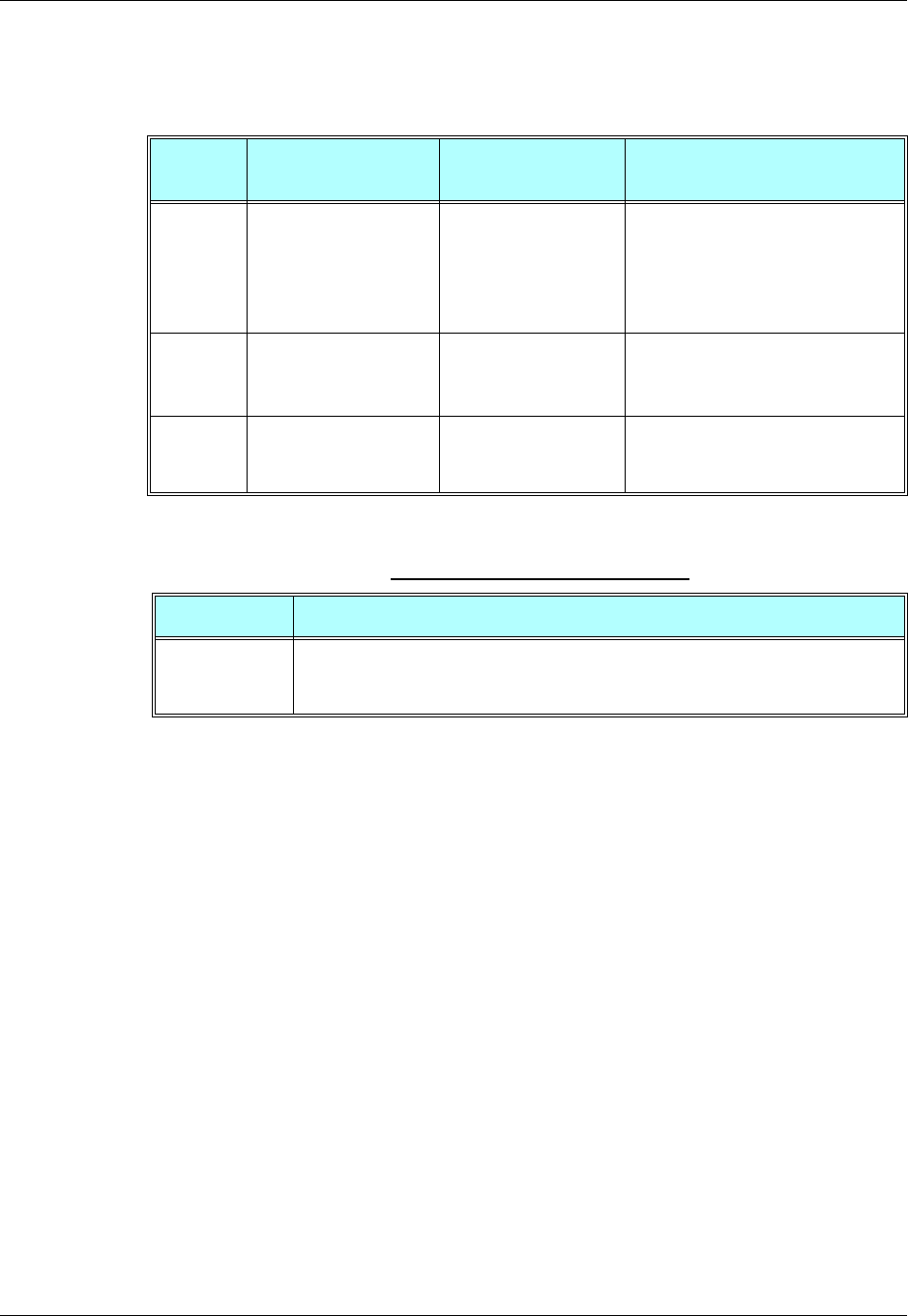
Table 3-120: +MPSU Parameters
<Parameter> Description
<activity> 0 - UART2 is closed.
1 - UART2 is open only for Logger use. In this case SPI Logger doesn't work.
2 - UART2 is open and work with full functionality.