
User guide

Canopy System User Guide Installing a BH Timing Slave
pmp-0229 (Mar 2013)
413
◦ Physically installing the BHS and performing a course alignment using the alignment tone
(Procedure 28).
◦ Verifying the BH link and finalizing alignment using review of power level and jitter, link
tests, and review of registration and session counts (Procedure 29 on Page 415).
Procedure 28: Installing the FSK BHS
1. Choose the best mounting location for the BHS.
2. Remove the base cover of the BHS. (See Figure 55 on Page 184.)
3. Terminate the UV outside grade Category 5 Ethernet cable with an RJ-45 connector, and
connect the cable to the BHS. (See Procedure 8 on Page 199.)
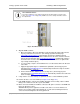
4. Attach the BHS to the arm of the Passive Reflector dish assembly as shown in Figure
135 on Page 398 or snap a LENS onto the BHS.
RECOMMENDATION:
The arm is molded to receive and properly aim the BH relative to the aim
of the dish. Use stainless steel hose clamps for the attachment.
5. Use stainless steel hose clamps or equivalent fasteners to lock the BHS into position.
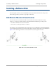
6. Remove the cover of the 600SS Surge Suppressor.
7. With the cable openings facing downward, mount the 600SS as close to the grounding
system (Protective Earth) as possible.
8. Using diagonal cutters or long nose pliers, remove the knockouts that cover the cable
openings to the 600SS.
9. Connect an Ethernet cable from the power adapter to either RJ-45 port of the 600SS.
10. Connect another Ethernet cable from the other RJ-45 port of the 600SS to the Ethernet
port of the BHS.
11. Refer to Grounding SMs on Page 178.
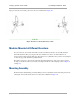
12. Wrap an AWG 10 (or 6mm
2
) copper wire around the Ground post of the 600SS.
13. Tighten the Ground post locking nut in the 600SS onto the copper wire.
14. Securely connect the copper wire to the grounding system (Protective Earth) according to
applicable regulations.
15. Connect a ground wire to the 600SS.
16. Replace the cover of the 600SS surge suppressor.
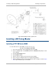
17. For coarse alignment of the BHS, use the Audible Alignment Tone feature as follows:
18. If the Configuration web page of the BHS contains a 2X Rate parameter, set it to
Disable.
a. At the BHS, connect the RJ-11 6-pin connector of the Alignment Tool Headset
(shown in Figure 139 on Page 402) to the RJ-11 utility port of the SM.
Alternatively, instead of using the Alignment Tool Headset, use an earpiece or small battery-
powered speaker connected to Pin 5 (alignment tone output) and Pin 6 (ground) of an RJ-11
connector.