
User guide

Canopy System User Guide Installing a BH Timing Master
pmp-0229 (Mar 2013)
411
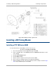
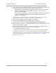
RECOMMENDATION:
The arm is molded to receive and properly aim the module relative to the aim of the
dish. ( See Figure 142 on Page 408.) Stainless steel hose clamps should be used for
the attachment.
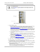
Figure 145: BH attachment to reflector arm
8. Align the BHM as follows:
a. Move the module to where the link will be unobstructed by the radio horizon and no
objects penetrate the Fresnel zone. (The Canopy System Calculator page
AntennaElevationCalcPage.xls
automatically calculates the minimum antenna
elevation that is required to extend the radio horizon to the other end of the link. The
Canopy System Calculator page
FresnelZoneCalcPage.xls automatically calculates
the Fresnel zone clearance that is required between the visual line of sight and the
top of a high-elevation object.)
b. Use a local map, compass, and/or GPS device as needed to determine the direction
to the BHS.
c. Apply the appropriate degree of downward or upward tilt. (The Canopy System
Calculator page DowntiltCalcPage.xls
automatically calculates the angle of antenna
downward tilt that is required.)
d. Ensure that the BHS is within the beam coverage area. (The Canopy System
Calculator page BeamwidthRadiiCalcPage.xls
automatically calculates the radii of the
beam coverage area.)
9. Using stainless steel hose clamps or equivalent fasteners, lock the BHM into position.
10. Remove the base cover of the BHM. (See Figure 55 on Page 184.)
11. If this BHM will not be connected to a CMM, optionally connect a utility cable to a GPS
timing source and then to the RJ-11 port of the BHM.
12. Either connect the BHM to the CMM or connect the DC power converter to the BHM and
then to an AC power source.
RESULT: When power is applied to a module or the unit is reset on the web-based
interface, the module requires approximately 25 seconds to boot. During this interval,
self-tests and other diagnostics are being performed.