
User guide


Installing an SM Installing Components
402
pmp-0229 (Mar 2013)
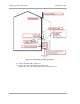
d. Connect the RJ-11 6-pin connector of the Alignment Tool Headset to the RJ-11 utility
port of the SM.
Alternatively, instead of using the Alignment Tool Headset, use an earpiece or small battery-
powered speaker connected to Pin 5 (alignment tone output) and Pin 6 (ground) of an RJ-11
connector.
e. Listen to the alignment tone for
◦ pitch, which indicates greater signal power (RSSI/dBm) by higher pitch.
◦ volume, which indicates better signal quality (lower jitter) by higher volume.
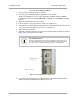
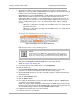
Figure 139: Audible Alignment Tone kit, including headset and connecting cable
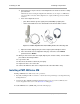
f. Adjust the module slightly until you hear the highest pitch and highest volume.
g. In the General tab of the Configuration web page of the SM, set the 2X Rate
parameter back to Enable.
32. When you have achieved the best signal (highest pitch, loudest volume), lock the SM in
place with the mounting hardware.
33. Log off of the SM.
34. Disconnect the Ethernet cable from your laptop.
35. Replace the base cover of the SM.
36. Connect the Ethernet cable to the computer that the subscriber will be using.
Installing a PMP 400 Series SM
Installing a PMP 400 Series SM consists of two procedures:
• Physically installing the SM on a residence or other location and performing a course alignment using
the alignment tone.
• Verifying the AP to SM link and finalizing alignment using review of power level, link tests, and
review of registration and session counts (Procedure 24 on Page 404).
To install a PMP 400 Series (OFDM) SM, perform the following steps.