
User guide


Installing an SM Installing Components
400
pmp-0229 (Mar 2013)
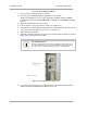
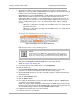
KEY TO CALLOUTS
1
Holes—for mounting the Surge Suppressor to a flat surface (such as
an outside wall). The distance between centers is 4.25 inches (108
mm).
2 RJ-45 connectors—One side (neither side is better than the other for
this purpose) connects to the product (AP, SM, BHM, BHS, or cluster
management module). The other connects to the AC adaptor’s
Ethernet connector.
3 Ground post—use heavy gauge (10 AWG or 6 mm
2
) copper wire for
connection. Refer to local electrical codes for exact specifications.
4 Ground Cable Opening—route the 10 AWG (6 mm
2
) ground cable
through this opening.
5 CAT-5 Cable Knockouts—route the two CAT-5 cables through these
openings, or alternatively through the Conduit Knockouts.
6 Conduit Knockouts—on the back of the case, near the bottom.
Available for installations where cable is routed through building
conduit.
Figure 137: Internal view of Canopy 600SS Surge Suppressor
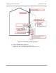
11. With the cable openings facing downward, mount the 600SS to the outside of the
subscriber premises, as close to the point where the Ethernet cable penetrates the
residence or building as possible, and as close to the grounding system (Protective
Earth) as possible.
12. Wrap an AWG 10 (or 6mm
2
) copper wire around the Ground post of the 600SS.
13. Tighten the Ground post locking nut in the 600SS onto the copper wire.
14. Securely connect the copper wire to the grounding system (Protective Earth) according to
applicable regulations.
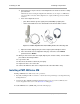
15. Using diagonal cutters or long nose pliers, remove the knockouts that cover the cable
openings to the 600SS.
16. Pack both of the surge suppressor Ethernet jacks with dielectric grease.
17. Wrap a splice loop in the loose end of the Ethernet cable from the SM.
18. Connect that cable to one of the Ethernet jacks.