
User guide


Installing an SM Installing Components
398
pmp-0229 (Mar 2013)
Procedure 22: Installing the FSK SM
1. Choose the best mounting location for the SM.
2. Select the type of mounting hardware appropriate for this location.
NOTE: For mounting 2.4, 5.2, 5.4, and 5.7 GHz SMs, Cambium offers the SMMB-1
mounting bracket. For mounting 900 MHz SMs, Cambium offers the SMMB-2 mounting
bracket.
3. Attach the mounting bracket to the structure.
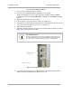
4. Remove the base cover of the SM. (See Figure 55 on Page 184.)
5. Terminate the UV outside grade Category 5 Ethernet cable with an RJ-45 connector, and
connect the cable to the SM. (See Procedure 8 on Page 199.)
6. Wrap a drip loop in the cable.
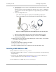
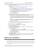
7. Optionally, attach the SM to the arm of the Passive Reflector dish assembly as shown in
Figure 135 or snap a LENS onto the SM.
RECOMMENDATION:
A reflector in this instance reduces the beamwidth to reduce interference.
The arm is molded to receive and properly aim the module relative to the
aim of the dish. Use stainless steel hose clamps for the attachment.
Figure 135: SM attachment to reflector arm
8. Use stainless steel hose clamps or equivalent fasteners to lock the SM into position.
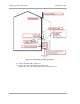
NOTE: The SM grounding method is shown in Figure 136.