
User guide

Adjusting Transmitter Output Power Configuring for the Destination
384
pmp-0229 (Mar 2013)
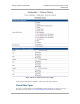
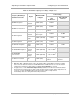
Table 60: Transmitter output power settings, example cases
Frequency Band Range
and Antenna Scheme
Region
Maximum EIRP
in Region
Transmitter Output
Power Setting
AP, SM, or BH
with
No Reflector
SM or BH with
Reflector
900-MHz Integrated
U.S.A.
Canada
36 dBm (4 W) 24 dBm
900-MHz Connectorized
U.S.A.
Canada
36 dBm (4 W) 26 dBm
1
Australia 30 dBm (1 W)
Depends on
antenna
2.4-GHz Integrated
U.S.A.
Canada
Depends on
antenna gain
25 dBm 25 dBm
CEPT
states
20 dBm (100 mW) 12 dBm 1 dBm
5.2-GHz Integrated
U.S.A.
Canada
30 dBm (1 W) 23 dBm
5.4-GHz FSK Integrated
CEPT
states
30 dBm (1 W) 23 dBm 5 dBm
5.4-GHz OFDM Integrated
U.S.A.
Canada
Europe
27 dBm (600 mW) −30 to 10 dBm
2
5.4-GHz OFDM
Connectorized
U.S.A.
Canada
Europe
27 dBm (600 mW) −30 to 15 dBm
2
5.7-GHz Connectorized UK 33 dBm (2 W)
Depends on
antenna
Depends on
antenna
NOTES:
1. With Mars, MTI, or Maxrad antenna. This is the default setting, and 28 dBm is the highest settable
value. The lower default correlates to 36 dBm EIRP where 10-dBi antennas are used. The default
setting for this parameter is applied whenever Set to Factory Defaults is selected.
2. In a typical case, set the Transmitter Output Power parameter in the AP to the maximum allowed.
This provides the greatest range for both overall operation and 3X operation. Where full power is not
necessary, or where the OFDM network is likely to interfere with a nearby network,
incrementally reduce the setting and monitor RF performance.