
User guide

Canopy System User Guide Adjusting Transmitter Output Power
pmp-0229 (Mar 2013)
383
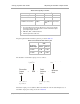
Table 58: Total gain per antenna
Module Type Antenna Gain Cable Loss
1
Net Gain
900-MHz Integrated 12.5 dBi 0.2 dB 12 dBi
900-MHz Connectorized
2
10 to 10.5 dBi 0.3 dB 10 dBi
5.7-GHz Connectorized settable
0.3 dB + from
any additional
cable
See Note 3
NOTES:
1. Received signal measurements take this loss into account, but the
transmitter output power setting cannot. Set the transmitter output
power higher by this amount.
2. With Mars, MTI, or Maxrad antenna.
3. Antenna gain minus cable loss.
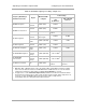
Integrated patch antenna and reflector gains are provided in Table 59.
Table 59: Patch antenna and reflector gain
Frequency
Band Range
Gain
Patch
Antenna Reflector
2.4 GHz 8 dBi 11dBi
5.2, 5.4, or
5.7 GHz
7 dBi 18dBi
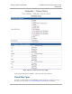
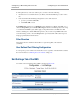
The calculation of transmitter output power is as follows:
Transmitter output power is settable as dBm on the Radio tab of the module. Example cases of
transmitter output power settings are shown in Table 60.
Tr a n s m i t t e r
Output
Power
=
EIRP
Pa t c h
Antenna
Gain
Reflector
Gain
- -
solve, then set
in parameter
from applicable
regulations
from the preceding
table
from the preceding
table