
User guide


Configuring an AP for the Destination Configuring for the Destination
250
pmp-0229 (Mar 2013)
Downlink Data
Specify the percentage of the aggregate throughput for the downlink (frames transmitted from the
AP to the subscriber). For example, if the aggregate (uplink and downlink total) throughput on the
AP is 6 Mb, then 75% specified for this parameter allocates 4.5 Mb for the downlink and 1.5 Mb
for the uplink. The default for this parameter is 75%.
CAUTION!
You must set this parameter exactly the same for all APs in a cluster.
Schedule Whitening
Select either
• Enable, to spread the transmitted signal power to avoid peaks that modules with Dynamic
Frequency Selection (DFS) configured might interpret as radar. This is the recommended
setting.
• Disable, to allow peaks in transmitted signal power.
PMP 400 Series OFDM APs do not have this parameter.
Control Slots
Field results have indicated that, in general, systems perform better with a slightly higher number
of control slots than previously recommended. If you are experiencing latency or SM-servicing
issues, increasing the number of control slots may increase system performance, depending on
traffic mix over time.
Use care when changing the control slot configuration of only some APs, because changes affect
the uplink/downlink ratio and can cause co-location issues. For APs in a cluster of mismatched
control slots settings, or where OFDM and FSK AP of the same frequency band are co-located,
use the frame calculator. See Using the Frame Calculator Tool (All) for Co-location on Page 542.
CAUTION!
Change control slot configuration in an operating, stable system cautiously and
with a back-out plan. After changing a control slot configuration, monitor the
system closely for problems as well as improvements in system performance.
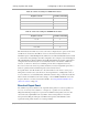
The recommended number of control slots is as stated in Table 49 or Table 50.