
User guide


Canopy System User Guide Configuring a Point-to-Multipoint Link for
Test
pmp-0229 (Mar 2013)
189
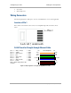
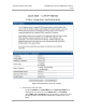
RJ-45 Pinout for Crossover Ethernet Cable
Pin 1 → white / orange ← Pin 3
Pin 2 → orange ← Pin 6
Pin 3 → white / green ← Pin 1
Pin 4 → blue ← Pin 4
Pin 5 → white / blue ← Pin 5
Pin 6 → green ← Pin 2
Pin 7 → white / brown ← Pin 7
Pin 8 → brown ← Pin 8
Pins 7 and 8 carry power to the modules.
Figure 58: RJ-45 pinout for crossover Ethernet cable
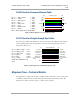
RJ-11 Pinout for Straight-through Sync Cable
The system uses a utility cable with RJ-11 connectors between the AP or BH and synchronization
pulse. Presuming CAT 5 cable and 6-pin RJ-11 connectors, the following diagram shows the
wiring of the cable for sync.
Pin
1 → white / orange ← Pin 1
Pin 2 → white / green ← Pin 2
Pin 3 → white / blue ← Pin 3
Pin 4 → green ← Pin 4
Pin 5 → blue ← Pin 5
Pin 6 → orange ← Pin 6
NOTE: The fourth pair is not
used.
Figure 59: RJ-11 pinout for straight-through sync cable
Alignment Tone—Technical Details
The alignment tone output from a module is available on Pin 5 of the RJ-11 connector, and ground
is available on Pin 6. Thus the load at the listening device should be between Pins 5 and 6. The
listening device may be a headset, earpiece, or battery-powered speaker.
7
8
TX+
TX-
RX+
RX-
3
6
1
4
5
2
7
8
RX+
RX-
TX+
TX-
1
2
3
4
5
6
+V
return
+V
+V
+V
return
Pin PinRJ-45 Crossover
1
2
3
4
5
6
1
2
3
4
5
6
sync pulse
serial transmit
serial receive
sync pulse
serial receive
serial transmit
override plug
alignment tone
override plug
alignment tone
no
t
used
no
t
used
Pi
Pi
RJ
-11 Straight-
Thru
Protective Earth (PE)
(ground)
Protective Earth (PE)
(ground)