
User guide


Configuring for Test Testing the Components
188
pmp-0229 (Mar 2013)
• wire cutters
• cable testing device
Wiring Connectors
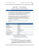
The following diagrams correlate pins to wire colors and illustrate crossovers where applicable.
Location of Pin 1
Pin 1, relative to the lock tab on the connector of a straight-through cable is located as shown
below.
Lock tab ↑ underneath
←
Pin 1
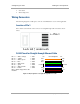
RJ-45 Pinout for Straight-through Ethernet Cable
Pin 1 → white / orange ← Pin 1
Pin 2 → orange ← Pin 2
Pin 3 → white / green ← Pin 3
Pin 4 → blue ← Pin 4
Pin 5 → white / blue ← Pin 5
Pin 6 → green ← Pin 6
Pin 7 → white / brown ← Pin 7
Pin 8 → brown ← Pin 8
Pins 7 and 8 carry power to the
modules.
Figure 57: RJ-45 pinout for straight-through Ethernet cable
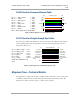
1
2
3
4
5
6
7
8
1
2
3
4
5
6
7
8
TX+
TX-
RX+
RX-
TX-
TX-
RX+
RX-
+V return
+V
Pin PinRJ-45 Straight-thru
+V return
+V