
User guide


Configuring for Test Testing the Components
186
pmp-0229 (Mar 2013)
Label
Color
when
Active
Status Information
Provided
Notes
SYN/1 yellow Presence of sync Always lit on the AP.
PWR red DC power Always lit when power is correctly supplied.
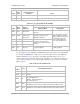
Table 47: Legacy Mode LEDs in SM and BHS
Label
Color
when
Active
Status if
Registered
Notes
Operating Mode Aiming Mode
LNK/5 green Ethernet link
Continuously lit when link is
present.
These five LEDs act as a bar
graph to indicate the relative
quality of alignment. As power
level and jitter (if present)
improve during alignment,
more of these LEDs are lit.
ACT/4 yellow
Presence of data
activity on the
Ethernet link
Flashes during data transfer.
Frequency of flash is not a
diagnostic indication.
GPS/3 red
Unused
If this module is not registered
to another, then these three
LEDs cycle on and off from left
to right.
SES/2 green
Unused
SYN/1 yellow Presence of sync
PWR red DC power
Always lit when power is
correctly supplied.
Always lit when power is
correctly supplied.
An optional light scheme configurable in all FSK SMs supports end customers who install the SM
(for example, the 9000SMQ indoor SM) on their own premises. The scheme uses the LEDs and
labels listed in Table 47 above, but is based on the traffic signal light analogy: green is good,
yellow is okay, and red is bad. This scheme can also be useful in some settings and workflows for
outdoor SMs. As with Legacy mode, while the SM is scanning, the green, yellow, and red LEDs
blink in sequence.
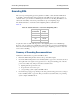
Table 48: Revised Mode LEDs in SM
Label
Color Revised Mode Indication
LNK/5 green
Link.
ACT/4 yellow
Activity.
GPS/3 red
Interference (Jitter)
On - high interference.
Blinking - medium interference.
Off - low interference.
SES/2 green
Strong Receive Signal Power
Blinking from slow to full-on to indicate strong power, getting stronger.
SYN/1 yellow
Medium Receive Signal Power
Blinking from slow to full-on to indicate medium power, getting stronger.