
User guide


Canopy System User Guide Configuring for Test
pmp-0229 (Mar 2013)
185
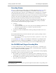
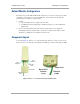
Figure 56: Base cover, detached and attached, OFDM module
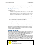
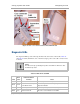
Diagnostic LEDs
The diagnostic LEDs report the following information about the status of the module. Table 46
and Table 47 identify the LEDs in order of their left-to-right position as the cable connections face
downward.
NOTE:
The LED color helps you distinguish position of the LED. The LED color does
not indicate any status.
Table 46: LEDs in AP and BHM
Label
Color
when
Active
Status Information
Provided
Notes
LNK/5 green Ethernet link Continuously lit when link is present.
ACT/4 yellow
Presence of data activity
on the Ethernet link
Flashes during data transfer. Frequency of flash is not a
diagnostic indication.
GPS/3 red Pulse of sync Continuously lit as pulse as AP receives pulse.
SES/2 green
Unused on the AP
SES is the session indicator on the CMM.